Making a plywood shoe rack on the LongMill

One material that I really enjoy milling on the CNC machine, either the Mill One or the LongMill, is plywood. It’s a strong, forgiving material that’s fairly inexpensive, with a decent sheet of  4′ x 8′ sanded 1/2″ plywood costing around $35 to $40 at Home Depot.

Some cut plywood pieces

The LongMill is designed to handle 2′ x 2′ sheets, specifically because you can take a 4′ x 8′ sheet and get exactly eight pieces from that (minus the cut width of the blade on one or two sides.

I just moved into a new apartment in Downtown Kitchener, and I realized that I didn’t have a shoe rack yet, so I figured that it would be a good project to do on the LongMill as a simple and quick test, and it would also let me get something useful out of it as well.

You can find all the design files and gcode here: https://www.thingiverse.com/thing:3178323

Want to make modifications to the design? Find the Onshape model here: https://cad.onshape.com/documents/a13ff69cba130fe9a7fbe081/w/e8122a12fba4c941c5dcb6f0/e/f80cc298643b4db924d45b1c

Here’s a quick video showing off the milling:

We’ll be at the grand opening of Conrad School of Entrepreneurship and Business

If you’ve been following us for some time, you might know that we’ve received a lot of support from the Conrad School of Entrepreneurship and Business. Well, we’ve been asked to join them for the grand opening of their new space in E7!

If you’re in the area and want to join us, we’ll be bringing by our machines to show off and doing demos.

Location: University of Waterloo E7 building

Time: Oct 29, 2018

  • 1 pm | Open House – Venture showcase
  • 3pm  | Engineering Grand Opening Ceremony
  • 4pm  | “How did we get from there to here? The Conrad Story” by Howard Armitage and Mark Weber
  • 5pm | Informal networking and connections. Refreshments served.

Tickets here:

https://ticketfi.com/event/2591/conrad-school-grand-opening

Sienci Labs is hosting its first beginners CNC milling workshop on Nov 13

Hey everyone. Just wanted to announce that we’ll be holding our first CNC milling workshop at our new space at 44 Gaukel in Downtown Kitchener in a few weeks!

Workshop attendees will get a chance to learn and design using CAD, create G-code using CAM, and cut out a design with a CNC machine.

To sign up and more info, please go to https://www.eventbrite.ca/e/beginner-cnc-milling-workshop-tickets-51654328487


LongMill updates: larger motors and more power!

I’ve been working with some of our first batch of beta testers who have reported issues with reliability, especially on the Y axis. If you missed that, you can read more about it here: https://sienci.com/2018/10/04/longmill-beta-y-axis-drifting/

There has been a couple of changes made to combat that. First was with adding a second power supply and an extra driver to the control box. This means upping the current, as well as putting less load on the Y axis driver, which had two motors wired in parallel.

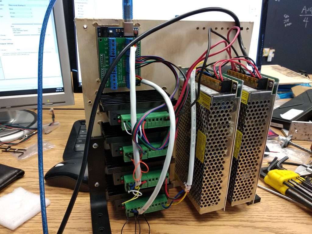
This should improve reliability by

  1. Giving more headroom for the power supplies
  2. The two Y axis drivers can be set to a lower current rating, so that the drivers don’t run as hot
  3. Reduce the chance of issues from back EMF and resonance from driving two motors on one driver

In production, we’ll probably switch to one large power supply and perhaps increase the voltage as well to make the electronics more simple and allow the machine to run faster, but as of right now, we have a lot of smaller power supplies tossing around that we can connect in parallel to do the job.

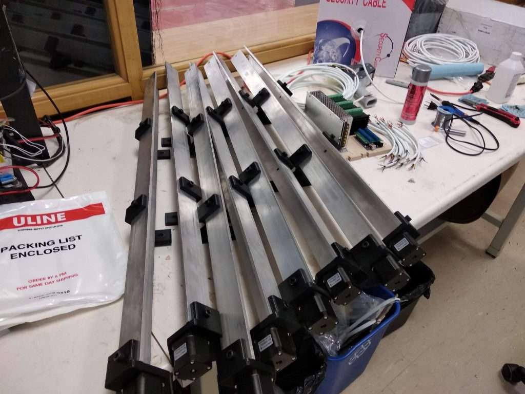
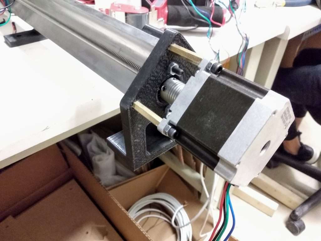
The other change has been to switch from NEMA 17 motors on the Y axis to using NEMA 23s (on the larger version of the LongMill). This should also improve reliability since

  1. NEMA 23 motors are rated for higher currents and torques, so that the machine can push through material faster.
  2. The larger body should help dissipate more heat

As for the smaller LongMills, the pair of NEMA 17s should be more than sufficient, but we’ll have to do some more testing to confirm.

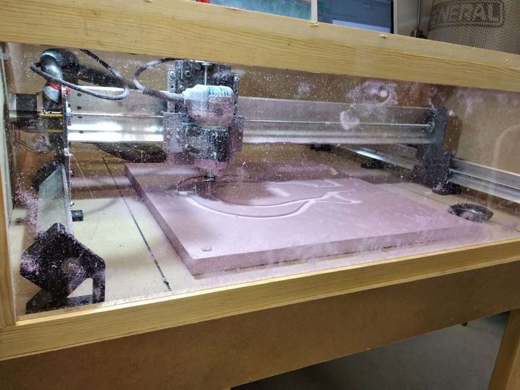
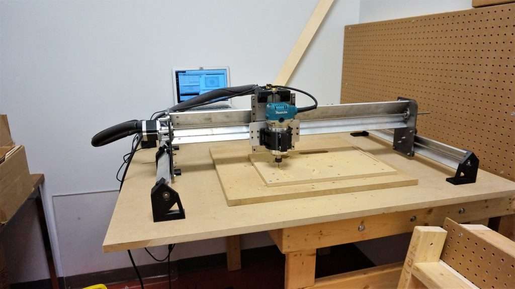
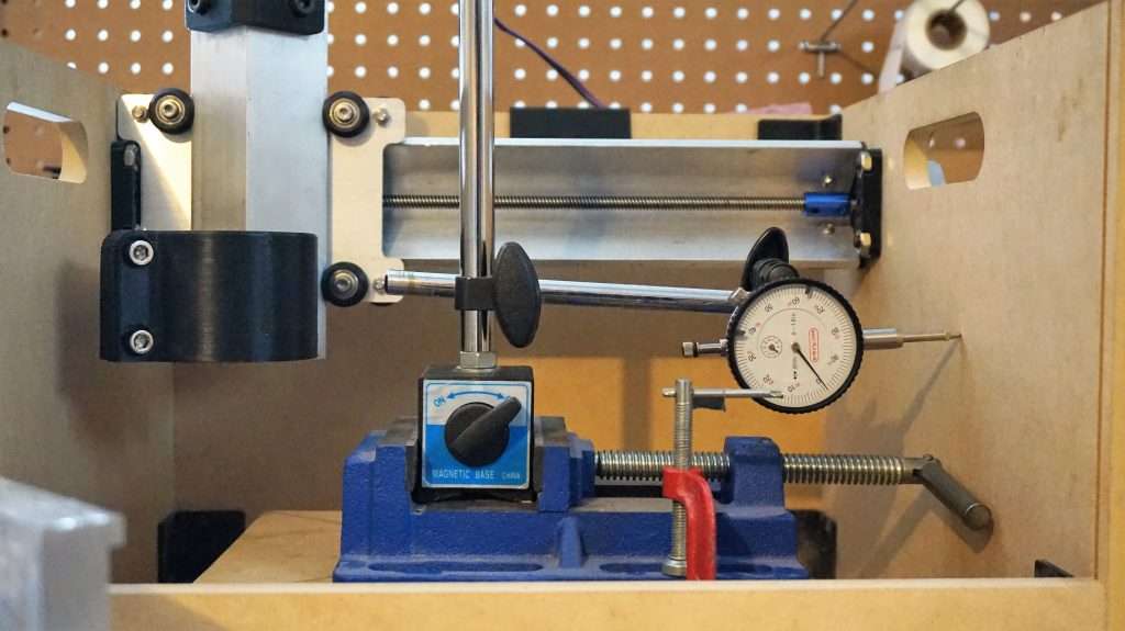
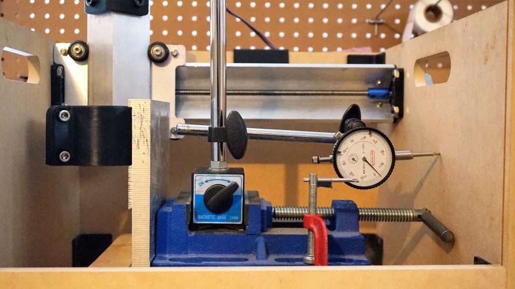
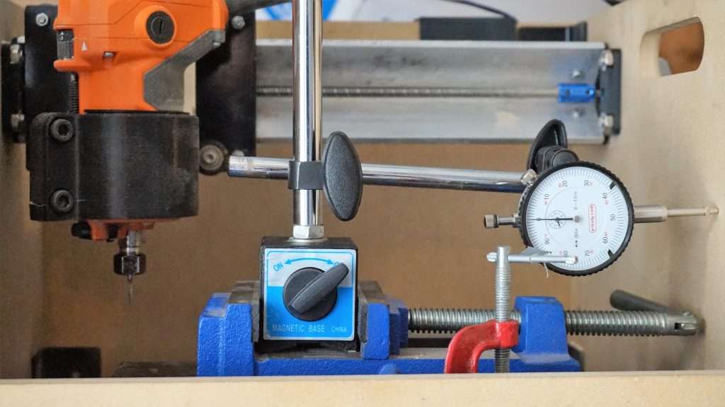
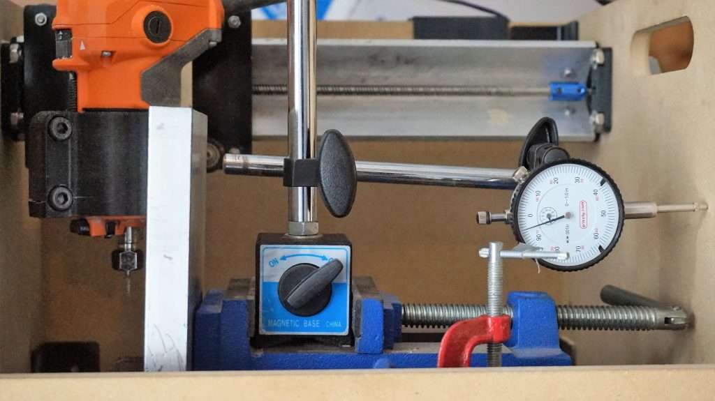
As so far as testing goes, I’ve been running the machine through a bunch of different projects, stress tests, and scenarios. I’m happy to say that there are significant improvements in speed and reliability. That being said, pushing the machine to the absolute limit artificially, such as moving the axis at max speed over the period of more than 15 hours, does still sometimes start to cause drifting and overheating on the motors. For normal milling, the projects are coming out perfect, so I will keep moving forward in updating machines and sending out new ones for now, and keep working to improve reliability.

If you’re reading this and you are one of the beta testers, here’s what you should know about your machines.

If you got your beta machine already:

I have already gotten in touch with you with info about the changes or I will have sent you this post as an update. I will update your hardware for you. Since there is a lot of extra hardware, it might take a little while for me to get all of the parts in to do the upgrades, so please be patient.

If you haven’t gotten your beta machines yet:

I will send out the machines with all of the updated hardware. Since there is a lot of extra hardware, it might take a little longer than the expected 3-4 weeks to get the machines out, but I am working as hard as I can to have the machines ready.

If you signed up as a beta tester and you haven’t gotten accepted into the program yet:

I am currently completing the second batch of orders that have come in from people interested in being beta testers. Initially, the plan was to start accepting people in for the third and last batch around this time of the month, but we are going to hold off on that until we are a bit more solid on the electronics and the first two batches have their machines up and running properly.

Joinery Box Project

One of the nice things about having a CNC machine is that it makes it super easy to make a lot of different types of joinery. This project shows how to make and mill out a simple box out of plywood. If you want to get some inspiration on some other designs for joining wood and other materials together, I would recommend taking a look at the Make Magazine’s CNC Panel Joinery Handbook.

You can find the models and gcode here (designed jointly by me Andy and Bojun Li): (upload the gcode and STL files to Thingiverse)

This article will cover some of the basic concepts around how this particular box was designed and how this very basic joint was designed. We’re using Onshape here, but you should be able to use whichever 3D CAD software you prefer. Just a quick note, the dimensions used in the diagrams below may not correspond with the actual dimensions of the box. The dimensions were just created as examples.

Male joint


There’s a couple of key dimensions here when creating the male part of the joint. First thing to look at is the 0.5″ dimension. This corresponds to the thickness of the material. Since the next piece of material will be 90 degrees to the joint material, having the width of the joint equal to the material thickness will ensure that the completed joint is flush on both sides of the box.

Next is the 0.125″ diameter dimension. This corresponds to the diameter of the end mill that you are using. CNC machines are unable to cut sharp inner radii, so we’re cutting in a bit further so that we can make sure that the two parts come together without interfering. Just a quick tip: sometimes your CAM software might not recognize the feature if your end mill diameter and your dimension are equal. If that happens, I’d recommend increasing the dimension a little bit until the CAM software does recognize it.

Lastly is the joint width (0.75″). You can change this to whatever you want.

Female joint

A lot of the dimensions here are going to correspond to the ones that we created above for the male joint.

First off, we have the 0.5″ dimension, which corresponds to the thickness of the material.

The 0.125″ diameter dimension corresponds with the end mill diameter as well, but this time, the sharp corner we are taking care of is in the inside of the joint. As I mentioned above, you can make this diameter just a tad bigger if your CAM software does not recognize it.

Lastly is the 0.75″ dimension. This should be the same as the width set for your male joint. You may find that if the joint is too tight or hard to put together, you can add a bit more space in this area to allow for a better fit (a few thousandths of an inch should do the trick).

Coming together

You should be able to line up all the joints on each side of your box so that you can fit it together once you mill it out. You can use 3D CAD software to “assemble” the box as well, to double check.

CAM

We’re using CAMLab to generate the gcode.

Here are some recommended settings:

  • Tool: 1/8″ flat end mill
  • Step down: 2mm-3mm
  • Feed rate: 800mm/min to 1000mm/min
  • Plunge rate: 250mm/min


Conclusion

I found that through doing this project, that figuring out all the joints and where to place them can be a bit tricky, but once you’ve made a few joints, making boxes on a CNC machine is super duper easy. I hope that this post can help get you on the right track on designing your own boxes. You can also get started by using our Onshape files and modifying them to fit with the dimensions you want.

Anyways, happy making!


Thingiverse: https://www.thingiverse.com/thing:3138612

LongMill Beta: Y Axis Drifting


So first things first, we’re going to call the “LongBoi CNC’s”… “LongMills” now. Feedback was saying that “Boi” was a bit too meme and unprofessional. LongMill sort of follows the Mill One name, except that it is longer, obviously. If you want to learn more, you can go to our landing page for the LongMill!

The first batch of beta testing machines are out in the world now, and they’ve settled in nicely. It’s cool to see that people have already made some enclosures and other things for their machine, as well as using them for their own projects.

This also helped uncover an issue that we are working to fix on some machines, which is that it appears that the Y-axis is drifting, usually after 30-45 minutes into a cut. From what I can tell, this is coming from the stepper motors on the Y-axis overheating.

We’ve already started testing and working on some redesigns to fix this issue and make the machine the best it can be, and changes will be rolled out to current users once we’ve completed this design cycle. I guess it’s both good news and bad news, bad news that there is still lots of work to put into getting this design and best it can be, but good news that I feel like the changes we’re planning on making to update the design will make it a much more powerful machine.

Stay tuned for more updates!


Beta CNC machines in production

Things have been really busy with the building and development of the LongBoi project. Progress is slow but steady. Some of the assembly was delayed since some of the parts were coming in slowly but we are on our suppliers and manufacturers to get parts in as soon as possible.

Here are a couple of changes that have been made from our initial designs:

  • Shorter belt loop between the Z-axis lead screw and motor. This brings the motor closer in toward the gantry and improves stiffness in the motor mount.
  • Redesigned Y-axis rail supports and motor mounts. The new design makes it easier to install and adjust M8 bolts along the rail.
  • Additional points across the machine to increase wire management options.
  • Polymer anti-backlash nuts on all axis.
  • Redesigned Y-axis gantry to move the router closer to the axis of rotation.

Stay tuned for more updates on this project!

Interested in becoming a beta tester? Sign up here: https://goo.gl/forms/Rei7ghZIDg6tlMhl2


“Big things” are coming to Sienci Labs. A new machine under development.

Over the one and a half years that the Mill One has been out in the wild, it has accomplished its role as a simple, affordable desktop CNC machine perfect for hobbyists and makers to dive into the world of CNC milling. We’ve designed a new machine (codename LongBoi) that holds that same focus, but as a new platform to allow for processing of larger materials.

It’s exciting to finally have this new machine out in the world for testing, especially since we’ve been working on the design on and off for the last couple of months. Here are our goals with the new machine:

  • Simplicity: The LongBoi holds the same philosophy as the Mill One to be a mechanical simple machine by reusing design cues throughout the machine, such as utilizing the angle aluminum v wheel design found on the Mill One and using a limited variety of parts.
  • Rigidity: The LongBoi has a 3×3 inch aluminum rail along the X axis, as well as a supported 2×2″ Y axis rail. The Z axis utilizes 12mm linear guides, allowing the Z axis to be rigid and extremely low profile. All gantries are made from 1/4″ steel or aluminum
  • Precision: Unlike some of the other larger, hobby grade desktop CNC routers like the X-Carve and Shapeoko, the LongBoi uses leadscrews on all axis, which means higher precision and no belt stretch.
  • Openness: The design of the LongBoi allows for a variety of modifications, especially with the simple design and use of 3D printed components. The Longboi uses standard and off the shelf parts that can be easily interchanged or replaced.

We currently have two sizes being beta tested, a machine with a 1ft x 1ft work area and a 2ft x 2ft work area. Want to be a beta tester as well? Check out this form to learn more and apply to be a beta tester! https://goo.gl/forms/Rei7ghZIDg6tlMhl2


Mystery packs now in store

A fun way to try new things on the Mill One is to try out new end mills and other hardware. That’s why we created the Mystery Pack! Sign up for the Mystery Pack and we’ll send you an assortment of cool stuff every month.

Are you interested in getting your hands on this Mystery Pack for free? Share your projects with us and we’ll send it to you completely free of charge. To sign up for free Mystery Packs, go to https://goo.gl/forms/ObkEJPFXMklOTBwB3 to sign up and for more details.

Testing with the Mill One V3 Y axis bed design

One of the parts that have been significantly changed on the Mill One V3 compared to the V1 and V2 is the design of the Y axis bed. We wanted to improve the rigidity of the Y axis, while allowing for more flexibility for wasteboard mounting and workholding. With this new two-part bed design, users can easily remove and switch out Y axis beds, and users can make their own beds if needed.

The steel Y axis gantry plate which will come with all V3 machines is far stiffer than the HDPE, which means a more rigid machine. You can see below based on some simple testing with a dial indicator and a 2-3 pound aluminum block, the difference in the amount of deflection that each machine experiences.

V3 deflection: Around 1-2 thousandths of an inch

V2 deflection: Around 5 thousandths of an inch


Testing on the V3 (without weight)
Testing on the V3 (with weight)
Testing on the V2 (without weight)
Testing on the V2 (with weight)

Testing was done on a very simple setup of a dial indicator pressing against the right side of each machine. The vice was lined up against the right edge of the bed for consistency. An aluminum block was placed on the opposite end. This allows us to compare the amount of deflection between the two designs.

One thing to note is that the Y axis gantry was an aluminum prototype that was milled out on the Mill One. Production machines will come with a laser cut steel gantry which is stiffer that aluminum. Because of this, we should be able to expect even better rigidity from production machines than from our prototypes.

Have a V2 machine but want to upgrade this part? You can get a kit that will update your machine here: https://sienci.com/product/v3-y-axis-bed-kit/