Hey everyone, over the past few weeks our engineers have been busy putting together feeds and speeds for the more rigid LongMill MK2, and Johann (one of the engineers) has decided to run the ultimate stress test by cutting a Versace Medallion in 6061 aluminum. The project features some big roughing cuts as well as precise finishing moves using four different cutting tools and we’d like to share the stunning results with you.
We used Fusion360 to generate the toolpath for this carve and the machining time was approximately 30 hours.
Click the links below to check out our new feeds and speeds page and see more information on the tools used.
Turn on REST machining and use climb milling when generating any of the following toolpaths.
Perform roughing with the first 3 tools using our suggested feeds and speeds. Leaving ~0.3mm of stock on all sides of the model. Use slotting step-down values for all 3 tools and values in the engraving section for the ⅛” ball end mill.
Optionally, run an additional parallel toolpath using the ⅛” ball end mill after you have completed roughing with the tool, again leaving ~0.3mm of stock on all sides (this will save you heaps of time running the ⅛” tapered bit).
Switch to the ⅛” tapered bit and run a roughing pass LEAVING ZERO STOCK. Feeds and speeds for cutting aluminum with a tapered bit is experimental so it’s only listed here at this time. 17000RPM | 1000mm/min Feedrate | 320mm/min Plunge Feedrate | 0.1mm Stepover | 0.12mm Stepdown
Shift your machine zero downwards by 0.12mm and run the finishing pass. You will need to lower your stepover to 0.02mm and exclusively use climb milling to obtain a good surface finish.
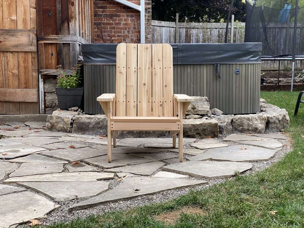
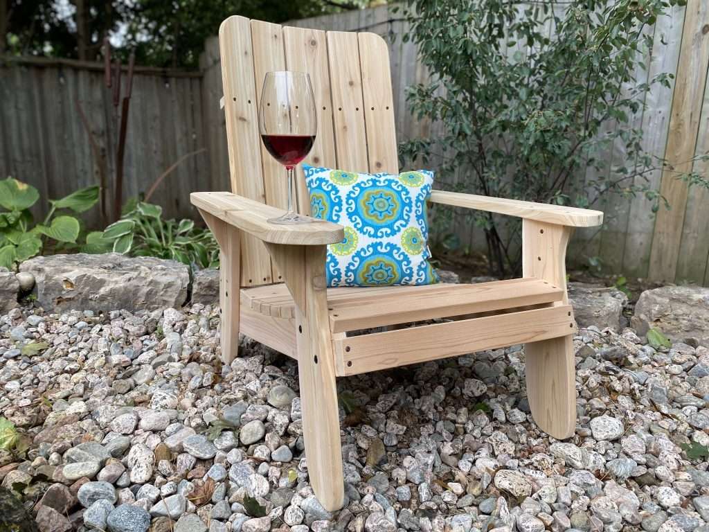
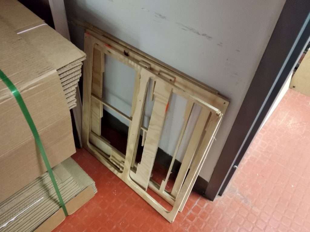
Hey folks. I’m excited to share a new project and all of the files and details to make an Adirondack/Muskoka chair on the LongMill! Scott, our in-house content creator and maker-supreme, wanted to add a few nice, high-quality chairs for his backyard, and so we set out to make a CNCable chair that can be made on the LongMill and basically any hobby CNC of a similar size.
This project was designed by me (Andy) and cut out by Scott in his shop. While this project has a lot of parts, the actual process to make them should be pretty straightforward since a lot of it is repetitive setup and cutting. While this is a perfect project for a beginner, I encourage advanced users to find ways to customize and modify our designs to add their own unique flair.
We continue our series of projects that you can make with your LongMill. To check out the one from before, visit our page here: https://sienci.com/2022/08/04/how-to-make-a-giant-connect-4-on-your-longmill. You can support us by subscribing to our Youtube channel and sharing projects that you’ve made from our designs online! If you have any ideas or projects you want to see us do, feel free to reach out or comment on our social media!
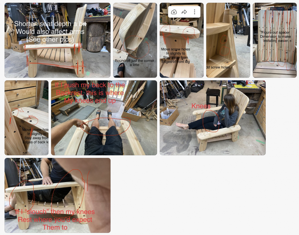
This was a bear to design. There were a lot of things we learned through the 4 or 5 different iterations it took to hammer it out. During the design process, it’s important for us to not just make a great design, but make it so that:
The materials you need for the project can be found universally and at a reasonable price
The materials can be of varying qualities but still work
The design can fit on a standard 30×30 working area
The tooling and techniques to make the project is accessible and easy enough for beginner users
Here’s what some back and forth looked like between me and Scott for making updates:
The newest version has some tweaks made compared to the version in the video which include:
Better placement of screw holes
Slightly shorter chair to fit knees better
If you see a design flaw, please feel free to let us know.
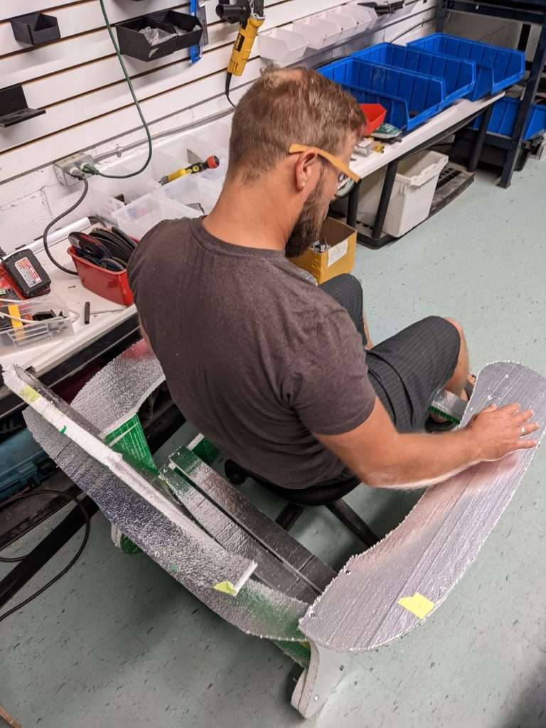
A foam test chair
Finding the right materials
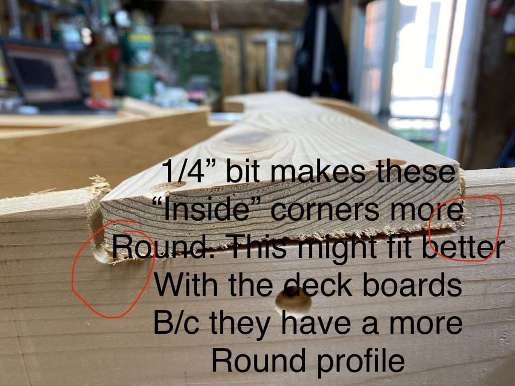
Finding the right materials for this project was a major challenge. Our first prototype used some 3/4″ cedar boards, but because lumber manufacturers are bad at measuring things, the actual thickness came out closer to 1/2″, but not to a degree of consistency that would let us make good joints without doing extra work planing and cutting down the boards. There was a lot of warp and cupping in the boards, making it even more difficult to fit things together. This resulted in poorly fitting parts and weak spots in the cut boards.
You can probably see it better in these photos and videos below:
3/4″ wood is strong enough for this project, so if you can get it while being dimensionally stable, I would probably get that stuff. The Onshape document does have some variables to help you adjust the size of the model based on the material thickness.
Another slightly annoying constraint was the widths of the wood we could buy for this project. It was important to us to use solid wood, at least for the sake of the asthetics that Scott wanted for his house, so we needed to use standard size boards. In our case, the best option was to use 6in wide boards (or 5.5 – 5.7in roughly), all of the parts needed to fit within that width.
According to Scott, this project uses about 56 feet of board (or 7 x 8 ft boards).
Slotting and lining things up
If you’ve seen some of the other designs I’ve made, I like to have things slot and fit together. The Connect 4 would be a good example.
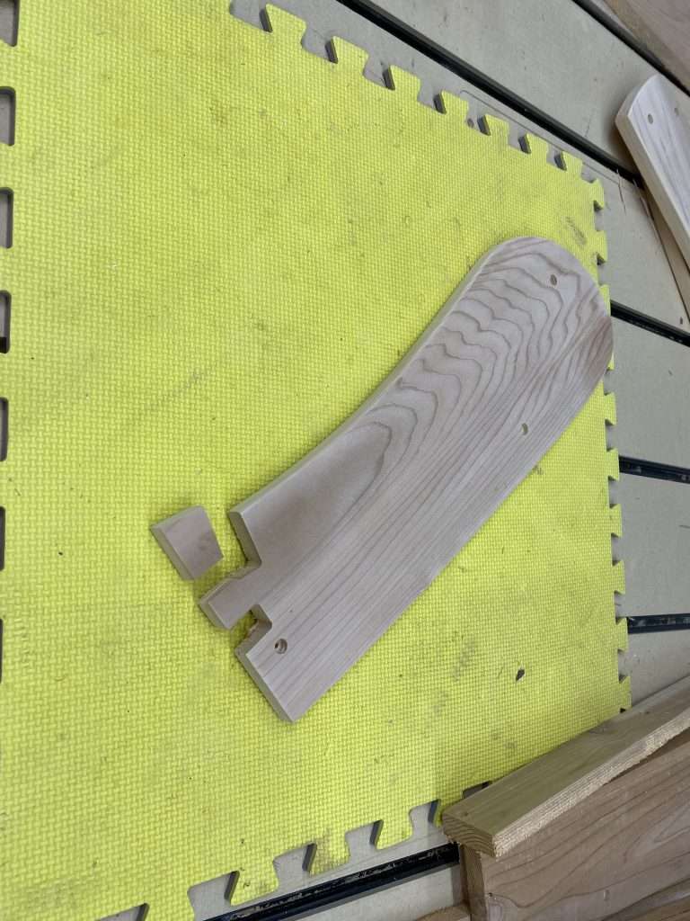
Well, given the variability of the thickness in the wood boards, even between throughout the board itself, it was hard to make a design that could actually have parts slot together. So I instead removed the need for things to slot together at all. This means that even if your material isn’t exactly the right thickness, you’ll still get a great chair. Basically all of the parts have a line or surface that can be used to line things up when putting the chair together (the arm support triangles are going to need a bit of eye-balling).
Cutting
Originally we had planned to cut the project using 1/4″ bit for the outside profiles and a 1/8″ bit for the holes, but we found that a 1/8″ bit for the whole project was a lot more convenient given that there’s no tool changes involved and less dust to clean up. Using the smaller bit does end up being a bit slower, but since this is a one-off project, time wasn’t a huge concern.
Cutting all of the parts should take about 2, maybe 3 hours. You can use feeds and speeds that you are comfortable with your material, but the gcode provided in the project files are set to 100IPM at 0.2″ depth of cut. It’s likely you can bump up the speed while cutting to your taste with the manual feedrate overrides.
Workholding
Scott suggests using hot glue as a way to keep the part coming out of its spot while cutting. I think this is a pretty good method overall, albiet a bit messy at times. For myself on the otherhand, I will cut the screw holes first and use them as a place to put some wood screws to keep the part in place as the outside gets cut out. Either method works.
Assembly
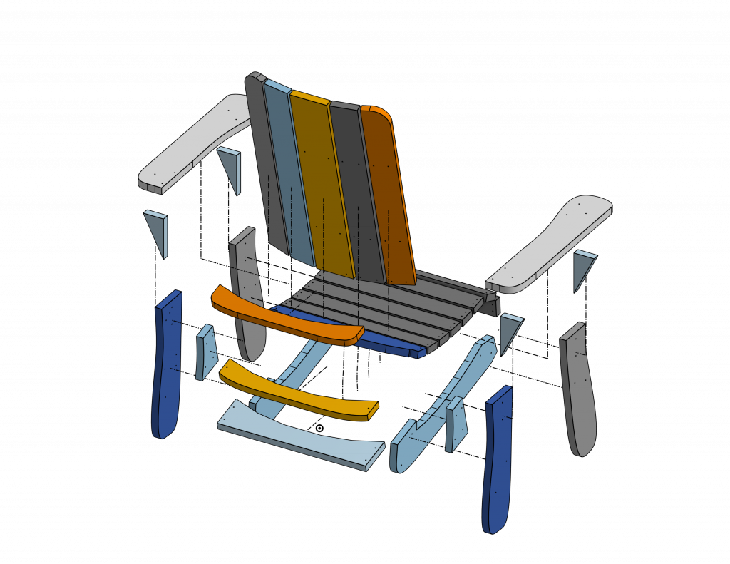
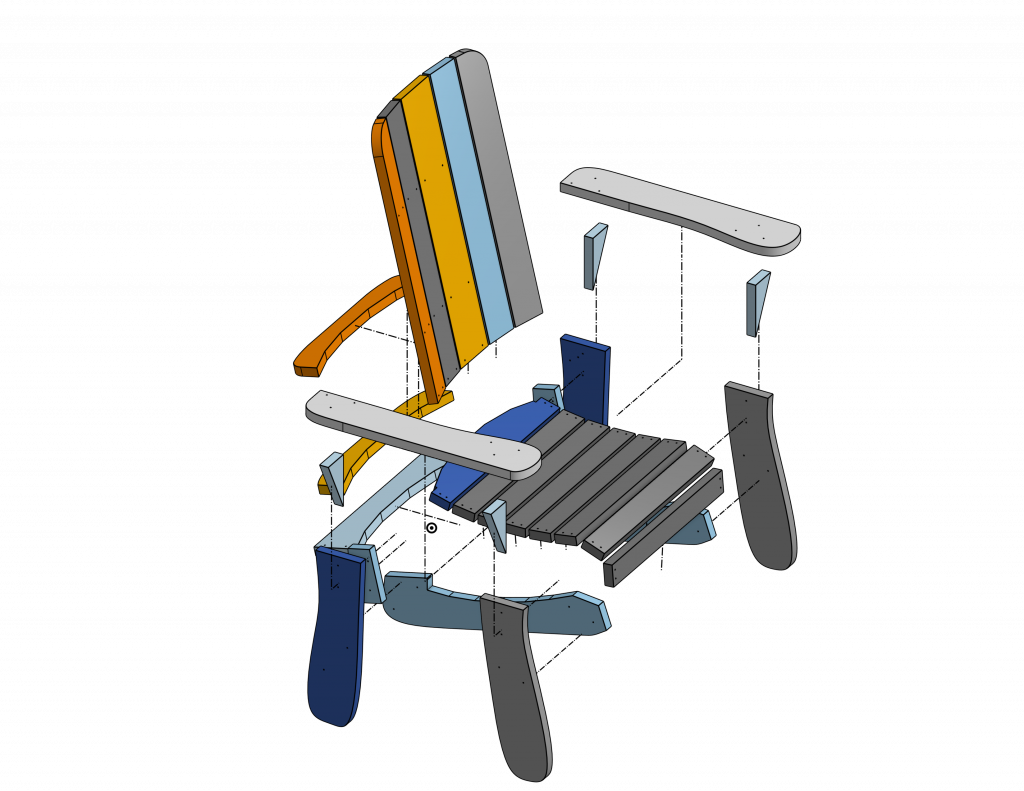
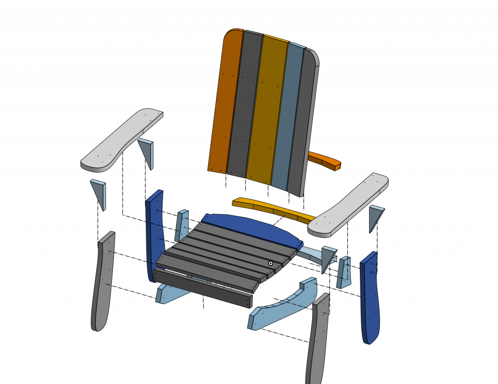
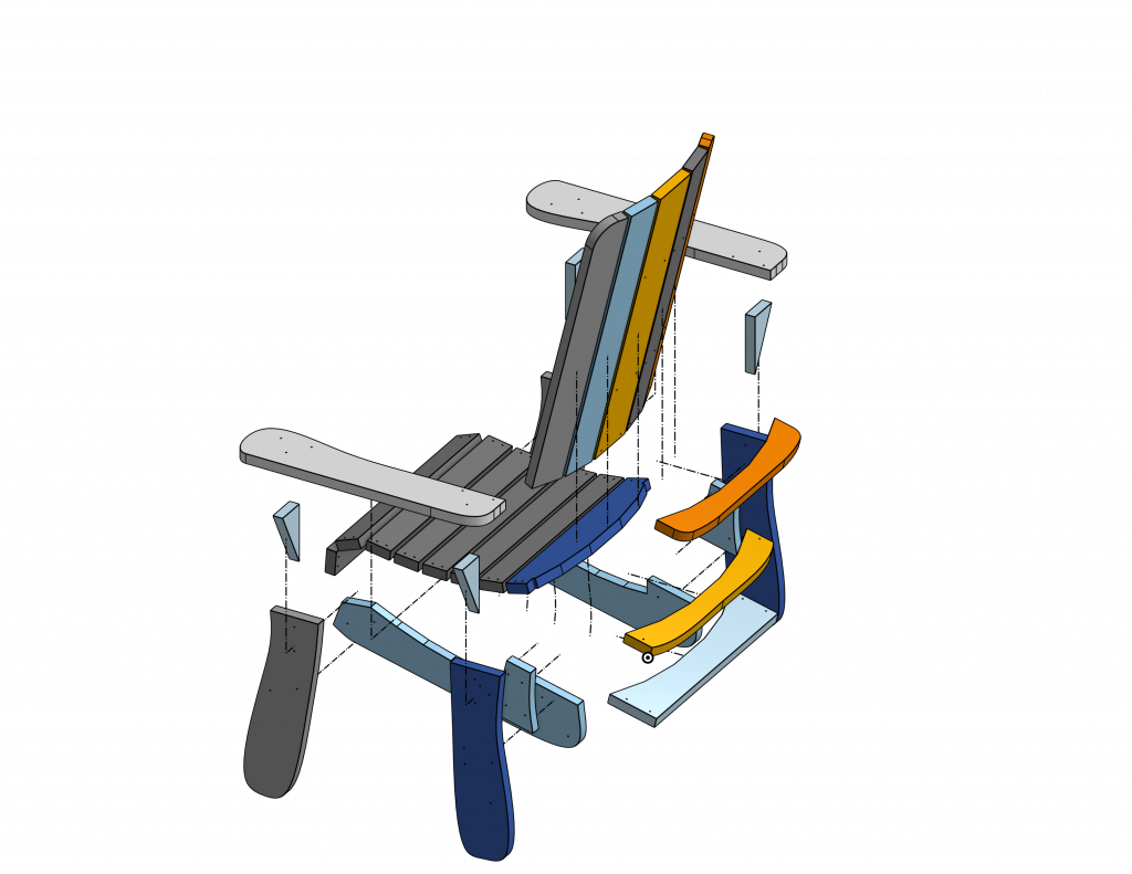
Please enjoy these exploded views of the chair. You can also check our 3D model as a reference for where things should go.
All of the parts are designed to fit together with quality, #8-1.5″ wood screws. Holes are pre-drilled with the CNC, but you may need to drill additional holes into support parts such as the triangles and the back supports.
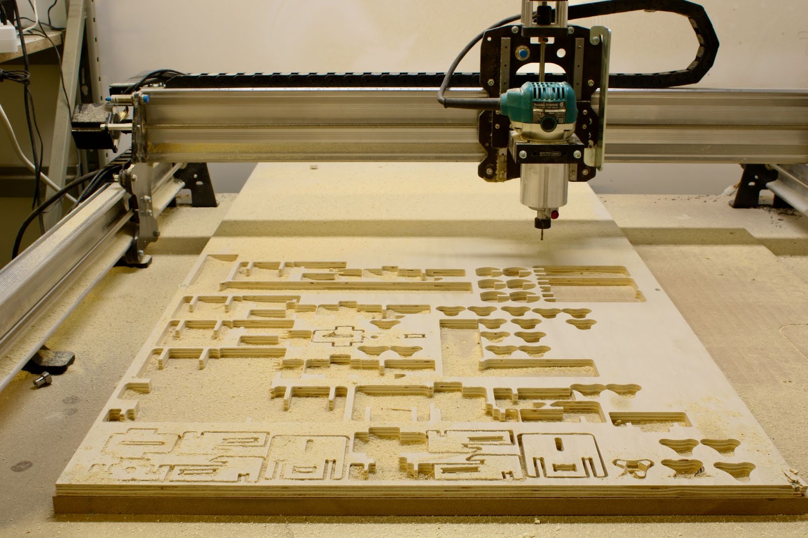
Hey everyone. We’re excited to share another really awesome project tutorial for your LongMill! If you want to check out the last project we did, please check out our article Make your own CNC workholding with your LongMill!
All you need for this project is a sheet of 1/2″ plywood and a 1/8″ end mill. Everything fits and slots together with friction and some persuasion with a mallet. If you want to use a different size material and modify the dimensions of the design, we’ve included a few variables that can be adjusted in Onshape for your specific materials.
By default, we made it so that the thickness of the wood is 0.5in, the thickness of each puck is 0.5in, and the diameter of the pucks are 3 inches in diameter. You can change the number in the variable to change the dimensions. If you use the pre-made project files and gcode, we’re assuming your material is 0.5in. Although most 0.5in plywood will work, if you want materials to fit perfectly, you can measure the thickness of your material with calipers, input that as a variable, and all of the slotting surfaces will automatically scale up or down, with additional clearance added in key areas to slot things smoothly.
Since the LongMill 30×30 is our most popular size, we’ve made everything work on the 30×30 size. Below is a diagram of how we broke down a 4×8 plywood sheet into sections for the LongMill.
Onshape offers a free, hobby and education use license that offers the full functionality of their program on the cloud, with the exception that all projects made on the free plan are public and searchable. This means that derivatives of this design will also be available to the public.
To modify designs, you will need to create an account on Onshape and duplicate/copy a new version to make changes. A few other notes:
When importing your DXF into a CAM program like Carbide Create or Vectric, please note that if they are coming out the wrong size, you may need to change your project units. I’ve found that setting the project units to inches usually works the best. Alternatively, you can scale them to the right size.
DXFs from Onshape are not usually joined, so you may need to use a “join vector” tool before creating toolpaths.
Most CNC users will likely want to export all of the parts as DXFs. This is a very easy process. Simply right-click the side of the model you wish to export the face of and “Export as DXF/DWG”. Then import the vectors into the CAM software.
For these projects, we used a 1/8″ end mill. Since we’re working with plywood, a down-cut end mill will work well, but a compression bit might work even better. You should be able to use any 1/8″ bit, but if you want to buy some from us, you can find them below:
If you are making your own gcode, you can adjust your speeds and feed accordingly. The gcode made for this project is fairly conservative and should work for pretty much any type of wood. You can increase and decrease your feeds and speeds using Feedrate Overrides in gSender or most feature filled gcode sender.
Here are some tips that might help otherwise.
Use ramping to help smooth out your cut. There are many small parts to this project that are prone to flying out. Ramping reduces the cutting loads when moving between each pass and prevents the part from breaking or shifting.
Use a smaller final pass. In some CAM software, you can set a final pass. This is the thickness of the last pass. By making the last pass smaller, you can prevent your part from flying out as the cutting loads are smaller.
This project was made with VCarve Pro, which has all these features. If you’re looking for free CAM software that can handle 2D DXFs for this project, I’d recommend Carbide Create as an excellent option.
Assembly
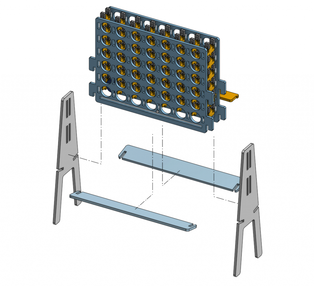
Start by cutting all of the parts out. You should end up with a couple of big parts and a bunch of small parts that keep all the big parts together. Here are a few exploded views to help out, but overall, the assembly can be found in the instructions.
A few notes:
Using some scrap wood to help direct your mallet blows will help keep your parts from breaking.
Putting in the “pirate teeth” on the one side first before assembling the second half, rather than putting both big sheets on first and putting the teeth on after, rather the way it was shown in the video may help keep things from shifting when assembling the two halves together. This will also help protect the tabs from breaking from the other side as well.
We’ve made some changes to the design between the video and the final public version to help things fit better and make tweaks. If you have some differences in your design, don’t worry too much as you’ll probably have the better version! However, if you run into any issues, feel free to reach out.
I hope everyone enjoys this new project. Stay tuned for new projects coming down the pipeline and make sure to subscribe to our Youtube!
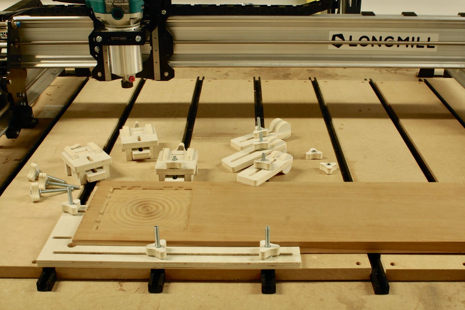
Hey everyone, we just wanted to share a quick and simple project to add some extra workholding options for your LongMill. This project also works great for other CNC machines so feel free to adapt them for whatever setup you have. We’ll be providing links to all of the files, gcode, and links to the parts and bits you need to use below.
One thing that we want to experiment with is in providing ready-to-run gcode to the community. Basically what that means is that rather than for us to provide the general design files, such as with a 3D model or vector file, users just need to have the right size material and bit to be able to create something. We believe that this will help lower the barrier for new beginners to do projects as they continue to learn to CNC. This also means users will be able to make stuff without needing to go through a CAM program, which we believe is one of the more challenging parts of the process. We’ll of course still be providing all of the other design files and info so that users can still modify and remake the files to their liking.
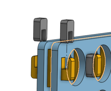
Clamps used for CNC workholding are always at the front lines of where the action happens, and because of this, are prone to getting chewed up or damaged. Having a CNCable design that can be made from scrap wood makes it easy to make extras whenever you need more or want to replace them. The goal for these designs is to be able to allow folks to make their own clamps using cheap and commonly available materials.
For these projects, you’ll need some
Plywood or other sheet material. We recommend using 3/8″ or 1/2″ material
1/4-20 hex bolts of various lengths. I’ve found 1-1/2″ and 2″ bolts are pretty good lengths to start with
We’ll also assume you have some sort of t-track or threaded inserts installed in your table as well. Depending on the t-track you have, you may need t-bolts that fit as well. If you’re looking for a t-track for the first time, I’d recommend finding some that have a profile that fit ¼” hex bolt heads instead, as compatible hardware will be easier to interchange and source.
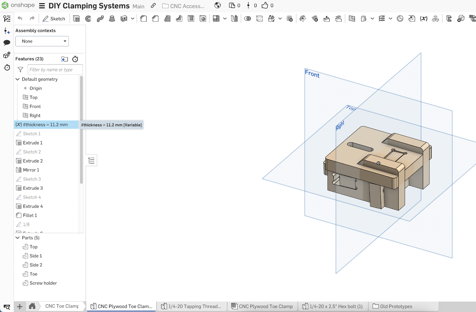
The pre-made files for this project are made for 3/8″ to 1/2″ plywood because they are common sizes, but if you want to use other thicknesses, the Onshape design document is publically available and can be adjusted to the materials you have on hand by changing the “thickness” variable on every Part Studio. The downloadable design and gcode files are pre-made for 3/8″ and 1/2″ material.
Onshape offers a free, hobby and education use license that offers the full functionality of their program on the cloud, with the exception that all projects made on the free plan are public and searchable. This means that derivatives of this design will also be available to the public.
To modify designs, you will need to create an account on Onshape and duplicate/copy a new version to make changes. A few other notes:
When importing your DXF into a CAM program like Carbide Create or Vectric, please note that if they are coming out the wrong size, you may need to change your project units. I’ve found that setting the project units to inches usually works the best. Alternatively, you can scale them to the right size.
DXFs from Onshape are not usually joined, so you may need to use a “join vector” tool before creating toolpaths.
Most CNC users will likely want to export all of the parts as DXFs. This is a very easy process. Simply right-click the side of the model you wish to export the face of and “Export as DXF/DWG”. Then import the vectors into the CAM software.
All of these clamps can be milled easily on a CNC machine and assembled by sliding the parts together. While the downloadable designs are made for 3/8″ and 1/2″ material, variations in the thickness of your material may affect how well parts slide together. For the most accurate fitment of parts, I recommend measuring your material’s thickness with calipers, then using that thickness plus 0.1mm on the “#thickness” variable in Onshape. This will automatically adjust areas of the design that rely on thickness, such as the joining slots and holes. That being said, some gentle persuasion with a mallet will usually do the trick as well.
Everything is designed to be cut with a 1/8” bit, and extra reliefs or “dogbones” have been added for everything to slot together nicely. Please note that if you use a different sized bit using our pre-made gcode, your parts will not come out to the correct size.
If you want to make your own gcode files, here are some general recommended settings.
If you want to get the cleanest looking cut, a downcut bit will work well and a compression bit will work even better. For the sake of accessibility, all of the designs have been made to work with ⅛” bits.
As a side note, I just wanted to mention about using corncob bits. Whenever I make slot-together projects, I actually generally use a 1/16” corncob bit because 1) it leaves a fairly clean top and bottom edge 2) has a thicker overall body, which makes it less prone to breaking compared to a fluted 1/16” bit 3) because it leaves most of the dust in the cutting path, most of the time I can get away without needing any tabs or something to keep the piece from flying out 4) since the radius is pretty small, a relief on the inner corner radius isn’t necessary for parts to fit together and 5) because the cuts are thinner, it also makes less dust and waste overall. Since ⅛” straight bits are almost ubiquitous, I’ve just made the designs work with those, but if you can get some 1/16” corncob bits to experiment with, I highly recommend it.
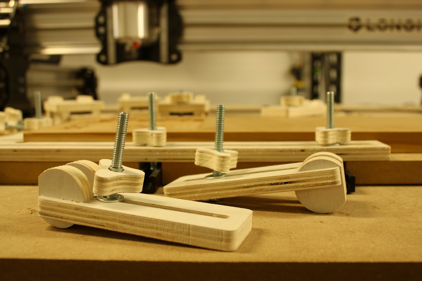
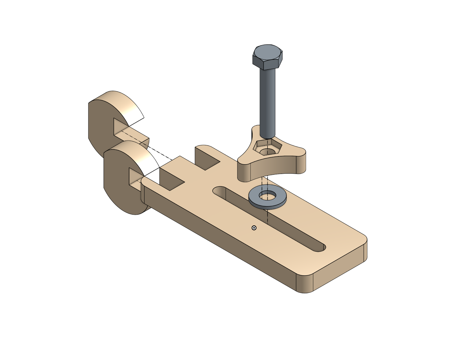
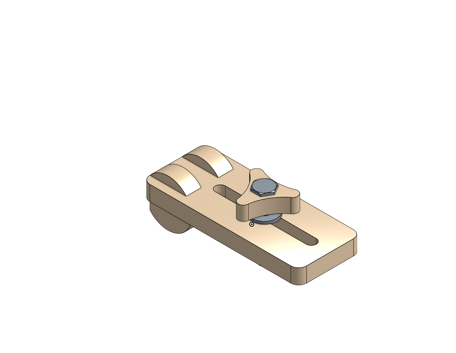
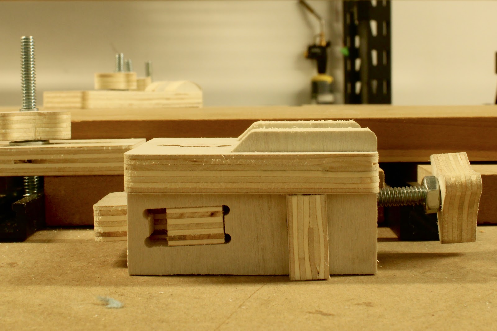
Project 1) Hold Down Clamps
Hold-down clamps are versatile and simple to use. They work by “holding-down” your material by pushing down on the top of the material.
There are a million different ways to make a hold-down clamp, but this design is unique as it uses a rounded support at the back to allow for the right angle to apply downwards pressure against your material. The most optimal angle for securing your material is at a level or slightly angled down position. Based on the thickness of your material, simply flip the clamp upside down to use the side that offers the most optimal angle.
Since these clamps are made of wood, even if you have a bit of an “oops” and run into them while carving, you’ll minimize the damage you’ll do to the machine and since you can make them on your CNC, you’ll basically have an unlimited supply!
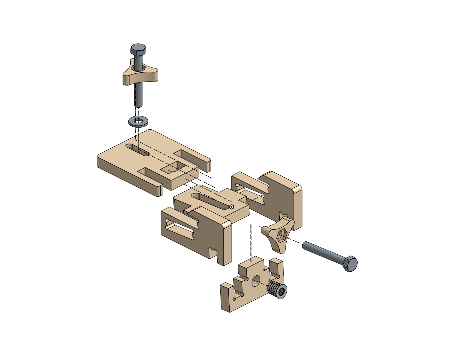
Exploded View
Tips, notes, and suggestions
Threaded inserts are super handy in adding threaded holes to wood. Simply fit a hex head driver or Allen wrench into the top end of the insert and screw it into the pilot hole. We sell these in the store but they are also easy to find on Amazon or at hardware stores.
Knobs and the semi-circles are prone to flying out after cutting, so I recommend milling them a little slower on the final pass than you would on the body of the clamp.
You’ll need different length bolts to accommodate different thicknesses of your project, but I’ve found that 1.5” and 2” bolts are suitable for most applications.
If you make the toe clamps in the next part of the article, make sure to make extra knobs as you’ll need them there too!
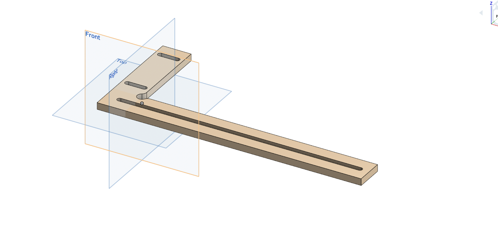
Project 2) Toe Clamp
If you don’t want to have clamps in the way of the top surface of your material, toe clamps are the way to go. By pushing in from the side, they stay away from the top of the material, and by angling the force downwards, we’re able to keep the material from lifting up as well.
This clamp must have some sort of hard stop for the other side of the material to butt up against. I’ve also included some designs for corner stops that can be bolted to a t-track table, but any solid stop for the material will work fine.
Tips, notes, and suggestions
If your clamp can’t get close enough to your material, try using some scrap blocks to fill in the gap. This can also help if your clamps are getting in the way of your spindle or router
Watch out that your clamp doesn’t slide away on the table when you turn the knob. Because of the mechanical leverage you get in the screw, the amount of force you’re putting on the material may be enough to slide away the clamp as well.
Final thoughts
I hope you find these designs useful and offer a starting point in building up your CNC workholding arsenal! Since these designs are freely open for you to use and modify, please feel free to make changes to the original design to make improvements and fit your needs.
We’re planning on continuing to design and share projects for our community, so make sure to subscribe on our social media.
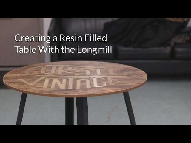
Patrik from Sienci Labs connected us with Alex from Curate Vintage to trade a custom made table for some custom Sienci Labs swag. In this project, we are carving the logo into a table using the LongMill and filling in the pocket with epoxy resin.
Software
For this particular project, we are using Easel by Inventables (http://easel.inventables.com/users/sign_in). Easel is a free, web-based, and simple to use CAM software that is excellent for beginners looking to do 2D projects like signs, trays, and lettering. Easel is compatible with many CNC machines, including X-Carves and Shapeokos.
There are many video tutorials on using Easel available online.
Importing an Image into Easel
By using Import — Image Trace on Easel, you can import JPG images to cut with your LongMill. Images that are black and white or made up of solid colors typically work best for this process. You can also watch this video (https://www.youtube.com/watch?v=Q-sfK-QxwzQ) which covers a slightly different method of using an image to create a carving.
Feeds and Speeds
The feeds and speeds used for this project was 60in/min (1524mm/min), 15in/min (381mm/min) plunge rate with a 0.125in (3.175mm) depth of cut. In the video the depth of cut says 0.18in, however since the pocket is shallower than the max depth of cut, it only cuts 0.125in down. These speeds are fairly conservative and should work with most types of woods.
End Mill
For this project, we used a ¼” downcut end mill (https://sienci.com/product/1-4-spiral-down-cut-end-mill/). We chose a downcut end mill because we knew that we would not be able to sand or finish the surface of the table after it had been cut or poured, as the surface would be ruined, and using a downcut end mill would prevent any splintering or fuzziness on the top surface.
Epoxy Resin
We bought 946mL of resin for this project and ended up using approximately 2/3s of it. This was our first time using epoxy, but we found it was a fairly easy process. Our particular resin required a 1 to 1 mix ratio which was measured out by scale. We added powdered color mica resin dye to provide the color. Our particular resin brand was called “ArtResin” which hardened in about 24 hours, but you can find an epoxy that fits your needs.
Project Learnings
This was a super fun project, and things turned out pretty well.
If we were to do this project again, we would probably want to use solid wood or high-quality plywood for the table material. This is because melamine covered MDF does not allow for us to sand or mill off the surface of the table. Instead, we needed to be careful to drip resin onto the uncut parts of the table.
Hey guys, check out our latest tutorial for your LongMill!
Taking images (JPEGs and other bitmap images) and carving them into wood and other materials is an awesome way to make signs and other projects. In this video, we’ll be walking through the steps on how to turn an image found on the web, making a v-carving, and carving it into a piece of material.
The description below covers some additional information that may not be covered in the video if you want to do some extra reading.
—Note: I personally use Inkscape and Carbide Create to do projects like these. There are many alternatives that you can use. Some programs that can also turn images into carvings include Easel and F-engrave. Your process and results may vary.
Tooling for v-carving:
A general purpose 60 degree or 90 degree v-bits for routering are quite easy to find, especially at your local woodworking or hardware store. If your project has a lot of wide lines, then typically a wider bit, like the 90 degree v-bit, would be preferred, as you don’t have to cut as deep to get a wide line. On the other hand, if your project has a lot of thin lines, using a narrower bit, like the 60 degree v-bit, can be a better option, as you can get a little more detail, and more contrast in the carving since it cuts deeper.
Speeds and feeds:
The general settings used in the video work well for most woods, but you should have a lot of headroom to play with on the LongMill if you choose to boost your speeds and feeds.
One other factor that can play a role in your cut time is your retract height. You may choose to lower your retract height to speed up your cut as well.
Material prep and finishing:
You will get the best results with material that is flat. This is because the variance in your material’s thickness can also cause variance in the width of your lines for your v-carving.
Having a contrast between the surface of the material and inside of the cut is important in ensuring that your carving is visible. For this particular project, I used melamine covered particle board, which has a reasonable contrast between the top white layer and the underlying brown particle board. Some methods of increasing contrast can be pre-painting the surface (paint outside of the cut), painting and sanding the surface (paint inside the cut), or choosing materials that have contrasting layers or surfaces (such as with color core HDPE)
Ideas and further learning:
You can use the first technique of turning images into vectors for a large number of other projects, such as with contour carving. If you have sketched artwork or hand-drawn pictures, you can also use photos of those items, as long as they have white backgrounds and are mono-colored.
One material that I really enjoy milling on the CNC machine, either the Mill One or the LongMill, is plywood. It’s a strong, forgiving material that’s fairly inexpensive, with a decent sheet of 4′ x 8′ sanded 1/2″ plywood costing around $35 to $40 at Home Depot.
Some cut plywood pieces
The LongMill is designed to handle 2′ x 2′ sheets, specifically because you can take a 4′ x 8′ sheet and get exactly eight pieces from that (minus the cut width of the blade on one or two sides.
I just moved into a new apartment in Downtown Kitchener, and I realized that I didn’t have a shoe rack yet, so I figured that it would be a good project to do on the LongMill as a simple and quick test, and it would also let me get something useful out of it as well.
One of the nice things about having a CNC machine is that it makes it super easy to make a lot of different types of joinery. This project shows how to make and mill out a simple box out of plywood. If you want to get some inspiration on some other designs for joining wood and other materials together, I would recommend taking a look at the Make Magazine’s CNC Panel Joinery Handbook.
You can find the models and gcode here (designed jointly by me Andy and Bojun Li): (upload the gcode and STL files to Thingiverse)
This article will cover some of the basic concepts around how this particular box was designed and how this very basic joint was designed. We’re using Onshape here, but you should be able to use whichever 3D CAD software you prefer. Just a quick note, the dimensions used in the diagrams below may not correspond with the actual dimensions of the box. The dimensions were just created as examples.
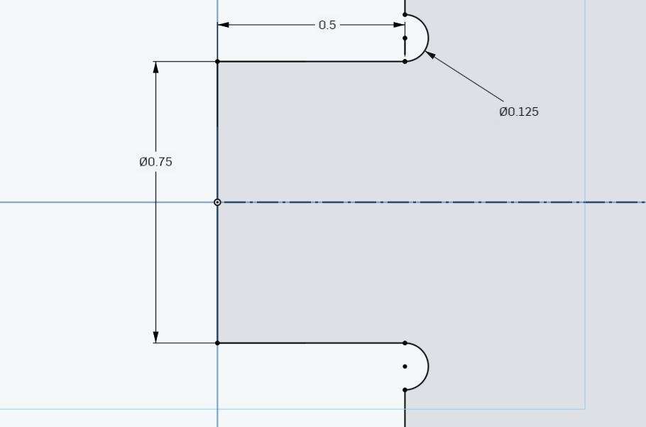
Male joint
There’s a couple of key dimensions here when creating the male part of the joint. First thing to look at is the 0.5″ dimension. This corresponds to the thickness of the material. Since the next piece of material will be 90 degrees to the joint material, having the width of the joint equal to the material thickness will ensure that the completed joint is flush on both sides of the box.
Next is the 0.125″ diameter dimension. This corresponds to the diameter of the end mill that you are using. CNC machines are unable to cut sharp inner radii, so we’re cutting in a bit further so that we can make sure that the two parts come together without interfering. Just a quick tip: sometimes your CAM software might not recognize the feature if your end mill diameter and your dimension are equal. If that happens, I’d recommend increasing the dimension a little bit until the CAM software does recognize it.
Lastly is the joint width (0.75″). You can change this to whatever you want.
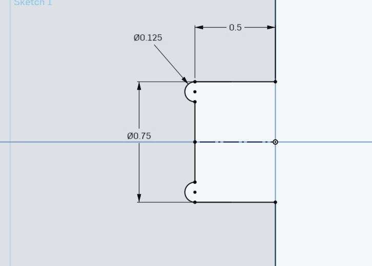
Female joint
A lot of the dimensions here are going to correspond to the ones that we created above for the male joint.
First off, we have the 0.5″ dimension, which corresponds to the thickness of the material.
The 0.125″ diameter dimension corresponds with the end mill diameter as well, but this time, the sharp corner we are taking care of is in the inside of the joint. As I mentioned above, you can make this diameter just a tad bigger if your CAM software does not recognize it.
Lastly is the 0.75″ dimension. This should be the same as the width set for your male joint. You may find that if the joint is too tight or hard to put together, you can add a bit more space in this area to allow for a better fit (a few thousandths of an inch should do the trick).
Coming together
You should be able to line up all the joints on each side of your box so that you can fit it together once you mill it out. You can use 3D CAD software to “assemble” the box as well, to double check.
I found that through doing this project, that figuring out all the joints and where to place them can be a bit tricky, but once you’ve made a few joints, making boxes on a CNC machine is super duper easy. I hope that this post can help get you on the right track on designing your own boxes. You can also get started by using our Onshape files and modifying them to fit with the dimensions you want.
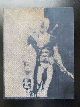
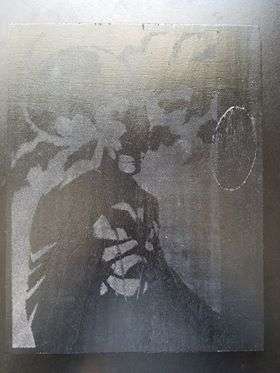
I recently stumbled upon this idea of milling halftone images and found it to be a neat way of transforming regular photographs into CNC millable projects. While it does work with any photograph, I have found that black and white drawings provide the best results, especially when working with a relatively small work area.
I created a youtube video on the process and chose to mill the following two images:
The software is relatively straightforward to use. You can set the angle of the bit you are using which in my case is a 30 degree v-engraving bit for the dead pool image and a 45 degree bit for the Batman image as well as the dimensions of the material you are working with. You can play around with the size and spacing of the dots depending on how detailed the image is and how detailed you want your print to be. The Deadpool print was simpler and as a result, required lower resolution. It ended up being comprised of around 22 000 dots while the more detailed Batman print was 35 000 dots.
Choosing the Material
The nature of this project requires that you have a very flat piece to mill on as even a slight variation in height can cause variations in the size of the dots. Having a different color beneath the surface of the material helps the dots stand out creating a more defined image. I decided to work with what I had and paint some poplar plywood black.
In my video, you can see I decided to sand and coat the plywood in wood glue prior to milling it. I found that the wood was slightly fuzzy and absorbed a lot of the paint I spayed creating a rough surface. Sanding removed the fuzziness while the wood glue made the surface even smoother and created a barrier keeping the paint on the surface which is why the finish on the Batman image looks significantly better than my first attempt with the Deadpool Image.
Milling the Piece
Halftone images are definitely one of the more time-consuming things to mill using the Mill One, especially when printing detailed images that can be comprised of over 30 000 dots. The Batman print in the video took over 8 hours. Reducing the depth of the dots and increasing the feed rate will help speed up the process. Another option is to use a bit with a higher angle which will allow the mill to create bigger holes at a shallower depth which is why I switched to a 45 degree bit for the second Batman image.
If you create your own halftone images, be sure to share them on the Mill One Facebook Group and If you have any questions about the projects I milled or need help milling yours, I encourage you to reach out.
So a couple of months ago I had a friend who asked me if I could scan and CNC mill a copy of her face. CNC milling? No problem, we could certainly do that. However, we didn’t have access to 3D scanning tools to create an accurate 3D scan of her face.
Accurate scanning tools that can capture a face at a high level of detail are somewhat expensive and hard to come by, but I have used the free app, 123D Catch (now discontinued), which allowed users to use a smartphone to create a 3D model. It was frustrating to use though, due to the fact that it could take forever to process the images into a 3D model, and resulted mixed results. It is also worth noting that using a scanner like 123D Catch needs the subject to be still for some period of time as the scanning takes place, and unless you have $60,000+ 360 degree scanning rig, it would be the case for most scanners. Needless to say, we shelved that project.
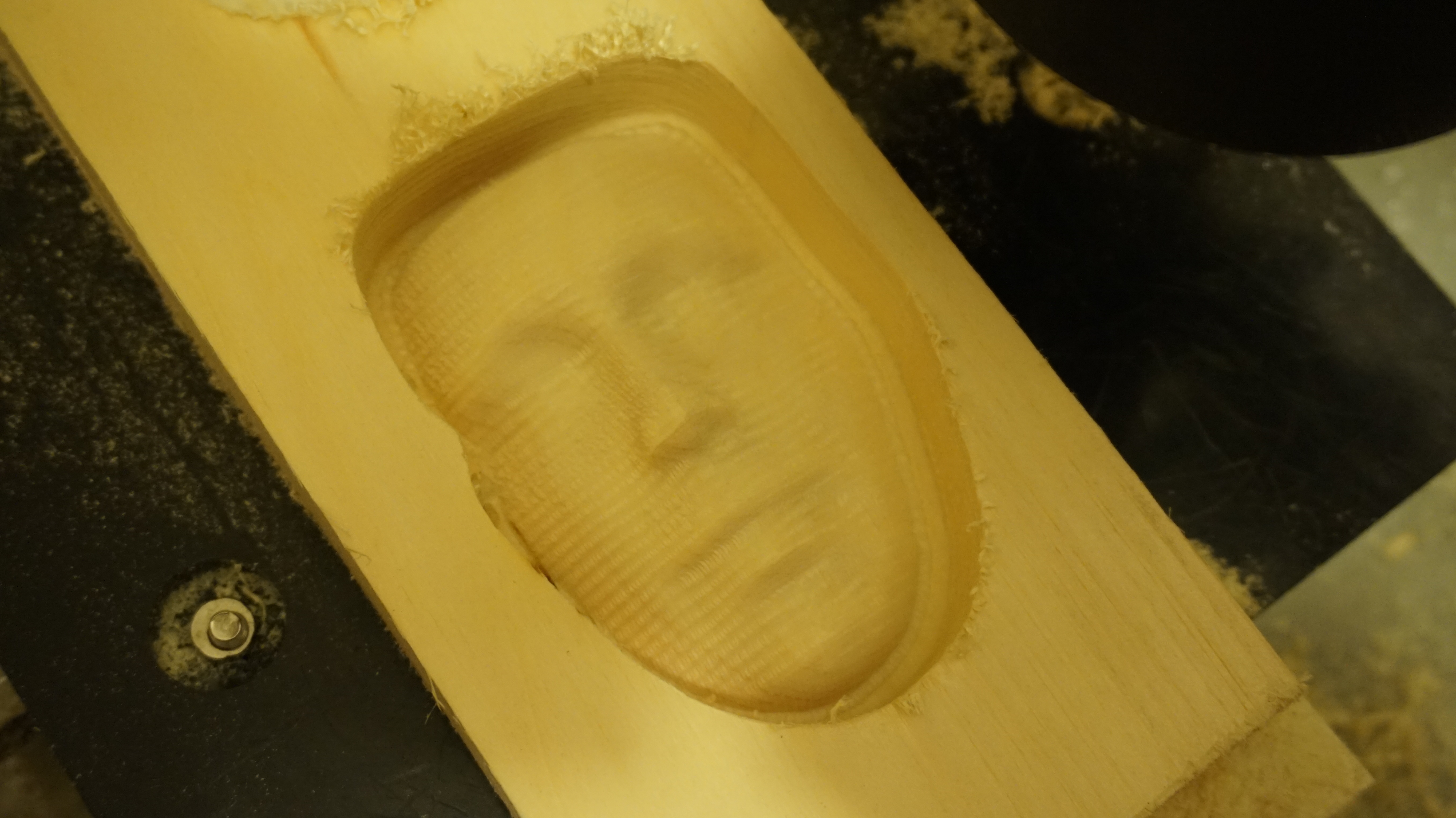
Then one day I came across this interesting project from the folks at the University of Nottingham, who had created a tool that could take a single picture and turn the face in the model into a 3D model. And so for fun, I decided I would try using a photo of one of our professors to create the 3D model.
So I took this model and converted it from a OBJ file and imported it into Kiri:Moto, then carved it out from some wood. Two tool changes and an hour and a half later, I had a little face in my hands.
Well what can I say. It looks like a face, although I don’t feel like the AI got it 100% right. I suppose we’ll have to see over the next few years how this technology progresses, but it looks like we won’t be getting super realistic masks out of the Mill One just yet.