Hey everyone, I’m excited to share with everyone a project that Chris and the rest of the Sienci Labs team have been working on in collaboration with Andrew and his team Expatria Technologies to develop a new CNC control board and firmware system. The SuperLongBoard (SLB for short) represents a huge step in hobby CNC technology, as it’s advanced electronics and software bring not just new features and functionality to the LongMill, but at a price point that we believe will be affordable for hobbyists.
What is the SuperLongBoard?
The SuperLongBoard is a next-generation control board for the LongMill CNC. This development gives access to a whole new set of features, functionality, and integrations more commonly found in industrial applications to the hobby CNC market. Some features and functionality include:
- Full integration of gSender within the control board, removing the need for a separate computer to run the CNC
- Advanced, programmable stepper drivers that run motors faster, quieter, and with more torque
- Faster, more accurate motion control processing for smoother movements
- Ability to control more than 3 axis, for full 4th and 5th axis motion control
- Networking and file transfer with wifi and ethernet, USB port and SD card for removable storage, HDMI output for display outputs, and more
- Standard PWM control for laser and spindle, with compatibility with industry-standard RS485 protocols for industrial-level spindle control
Additionally, this design will have many input-output connections and ports to allow for new features and accessories to be used with the new board, effectively future-proofing your machine for years to come. Some of these features include:
- Automatic tool changing support
- Skew, cutter, and joint compensation
- External wired and wireless pendant control
- Camera and machine vision for features like failure and crash detection, auto zeroing, auto-tracing, and more
Please note that although these features are something we want to work on down the line, we currently do not have specific timelines on these features and they will not be available during launch.
The SLB is a system of two different parts working together. The first is the board itself, which contains all of the core functionality. This includes motor control, sensor inputs and outputs, and lower-level processing of g-code. Users will be able to tether this part of the controller directly to the computer using a USB cable in the same way as the original LongBoard currently used in all LongMills to control their CNC machines.
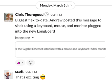
SLB takes things to the next step with the addition of an onboard compute module. The SLB has a small connection interface at the bottom of the board that allows for a compute module to be attached and replaces the computer or laptop. Users can connect a keyboard, mouse, and monitor to control all functions of the machine directly through the SLB.
The SLB can operate with and without the compute module. I expect that given the considerably low price of the compute module over a computer, around $40-80 dollars plus the cost of the monitor, keyboard, and mouse, as well as the extra speed, user experience, and reliability of an onboard system. But we are planning to allow for the board to be used in either configuration.
This control board will be backward compatible with ALL LONGMILL CNC MACHINES OF ALL GENERATIONS, which means that users can upgrade their machine’s capabilities by simply replacing the controller. All of the hardware and software will come ready to go, plug and play for all LongMill CNCs, and will have a similar form factor to the current LongBoard so that it can be integrated easily into your existing machine.
Why the SuperLongBoard?
The creation of the SLB comes with a series of motivations. The first and main motivation is our belief that at this current stage, the integration of smarter, more reliable, and more capable CNC control electronics will make the biggest improvement to the CNC user experience.
This new design will aim to eliminate many common issues universal to hobby CNC at this time, including:
- Electromagnetic interference issues
- Computer, compatibility, and connection-related issues
- Resonance and driving issues restricting motor performance
With the integration of an onboard computer and far more sophisticated electronic systems, the SLB will not only be able to eliminate these issues, but it will also allow us to have better control of the hardware and software to optimize every aspect of the board and iron out bugs more easily.
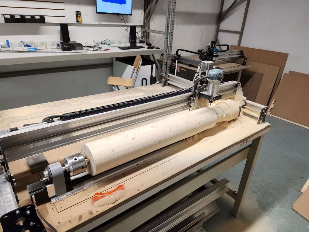
As some readers know, we’re also in active development of the rotary axis. The SLB will also open up more possibilities for integrating new add-ons and improving already existing add-ons such as the AutoZero touchplate and LaserBeam. Some other potential add-ons include:
- Plug-and-play router or spindle with programmable speed control
- Bitsetter
- Toolchanger
- Plasma cutter
There are no specific development timelines for these items, but the SLB will allow for better compatibility for add-ons such as the ones listed above.
Development of the SuperLongBoard
The SuperLongBoard has been in development since the Fall of 2022. We’ve received our first batch of prototype boards and have been working with Andrew to develop the firmware and software for the control boards, finalize the PCB design, and prepare them for long-term beta testing.
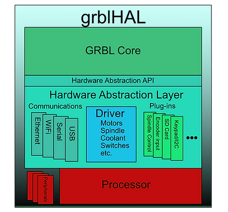
The development of the SLB actually comes with many different individual developments that all work hand in hand. First is the integration of grblHAL, a rewrite of GRBL that was originally designed to work on Arduino-based controllers. One of the limitations of GRBL was that since it was designed to work on low-performance microcontrollers, it has limitations on what features that could be added. Additionally, there are limitations on things like how many processes could happen at any given point and the raw speed of the processing of g-code and motor signals.
grblHAL essentially uses something called a hardware abstraction layer (HAL). The HAL is essentially like a switchboard that the GRBL core knows how to use the microcontroller to communicate with different aspects of the board, such as the spindle control, motor drivers, and networking. This means that the development of core firmware that includes all of the functionality can be developed and only the HAL needs to be adapted to each model of the microprocessor. This means that the development of grblHAL benefits the whole community since features that are developed for one controller can be implemented on other controllers almost immediately with basically no modification. grblHAL, although still fairly new, already has a fair number of plugins that can be used to add functionalities.
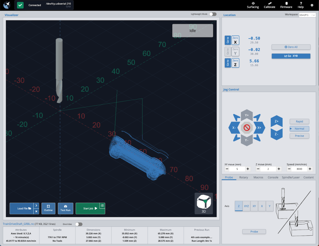
The next part of the development is with the gSender integration into the SLB and to use grblHAL. Since the plan is to integrate gSender directly on the compute module, we are working on optimizing it for the hardware, such as improving the general performance and UI, adding new features and functionality, and testing the speed and reliability of gSender as a whole. We’re already working on the new gSender, and you can find an early access version here.
And lastly comes the design and production of the PCBs themselves. At this stage, we’ve mostly finalized the design of the board and are making the last few touches to the design and layout. The new control board uses a larger number of components, adding to the challenge and complexity in manufacturing, but we’ve been able to work closely with PCB manufacturers for the first batch of prototypes and expect this area to come along relatively smoothly.
We are expecting to work on testing the boards in-house for the next few weeks and start beta testing in the next coming months.
Pricing
At this time, we’re expecting the manufacturing and production cost of the SLB and case to cost around $100 (prices here in CAD). The compute module is expected to cost between $40 to $80 depending on the model and spec, bringing the total cost of production to around $150.
Chris and I have been talking about the pricing and how we want to figure this out, but we do have a few goals:
- To offer it with new LongMill machine kits with minor changes to the current price
- To have a simple and inexpensive upgrade path from the original LongBoard to the SBL
- Reduce buyers remorse for currently existing customers
Here is our tentative pricing. Please note that pricing may change and is not set in stone.
SuperLongBoard, onboard computer, and enclosure: $280CAD/$210USD
This would be the full package with everything you need to plug and play with any LongMill. This also includes the onboard computer. Users who wish to use the onboard computer will need to provide their own monitor, keyboard, and mouse.
If you want to mix and match parts, you can use the pricing estimates below:
SuperLongBoard only: $180CAD/$140USD
For users that only want to upgrade the controller, but do not have the onboard computer. This would mean that you would still need to connect a laptop or computer to your controller. This also doesn’t include the price of an enclosure, so users can either make their own or integrate it with an existing enclosure. The case for this version of the controller is not backward compatible with the original LongBoard currently used in the MK1 and MK2 LongMills.
Onboard computer: $80CAD/$60USD
The onboard compute module is essentially a Raspberry Pi CM4 or another compute module of the same form factor. There are many different versions of CM4 form factor modules, all of which have different price ranges and specs. The price points of these modules vary greatly, which means the specific cost of this will be tied to which module we decide to choose. This would be available to users who choose to start with the SuperLongBoard and decide to add the onboard computer later in the future.
Enclosure: $30CAD/$23USD
The enclosure serves to protect the controller from dust and damage, as well as provide some mounting options onto the LongMill.
What’s next?
With regard to the LongMill
Once we get the SuperLongBoard into production, customers will be able to order them from our store to upgrade their machine electronics or as the controller that ships with new LongMills.
Here is our current general plan:
- Once the SuperLongBoard is launched, to offer the original LongBoard and SuperLongBoard as separate options. The option for the original LongBoard would be the same, and the SuperLongBoard option would be a little more expensive.
- Once we run out of or decide to phase out the original LongBoard, all new LongMills will ship with the SuperLongBoard.
- For existing LongMill customers, we may provide a coupon so that users who wish to upgrade to the new controller can do so at a lower cost.
Based on where we are in current development, we expect SLB available sometime in the late fall or winter of 2023.
The exact details and pricing will come later.
With regards to other CNC machines
Given how powerful and integrated the SuperLongBoard is, we expect other CNC users to want to integrate the board with their own machines. While the board itself isn’t expected to cost a lot, given the complexity of support, resources, and documentation, we expect that a significant consideration in terms of support and price point will come down to many different factors.
We do plan on releasing the board designs open source as we have done for all of our hardware and software, which means that even if we don’t provide any official support, users who want to tinker should be able to figure out how to integrate things.
Here is our current general plan:
- Users who want to use this board for other machines will be able to purchase it from our store, but they will not receive any technical or setup support. We will provide resources that we feel will be adequate for an experienced user to use for setup. At some point, we may also set up an online community where people can help each other.
- In the future, there may be a certain tipping point in terms of scale for us to offer specific machine support, or if a third party decides to provide support themselves.
SuperLongBoard Survey
If you want to help contribute to our development for the SLB, please feel free to do our survey!
Link to the survey: https://forms.gle/7ujAmjZ7LGwdjMjT7
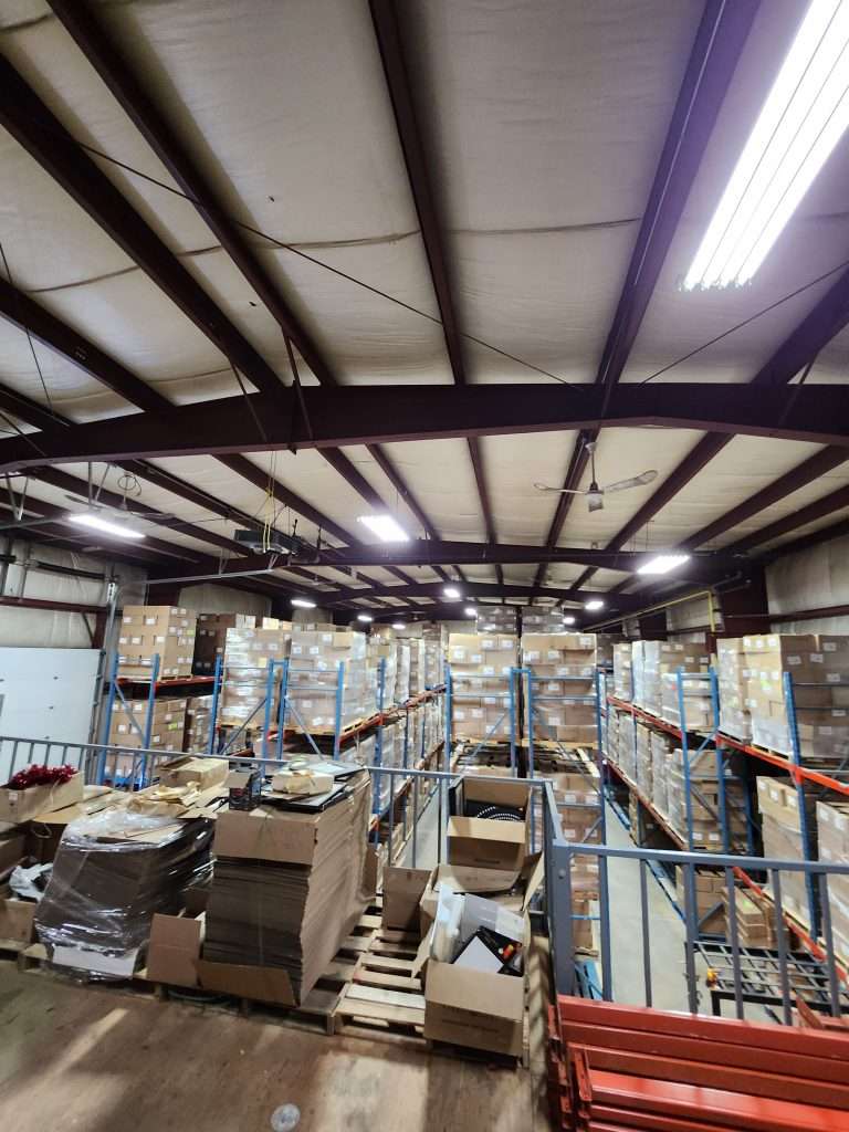
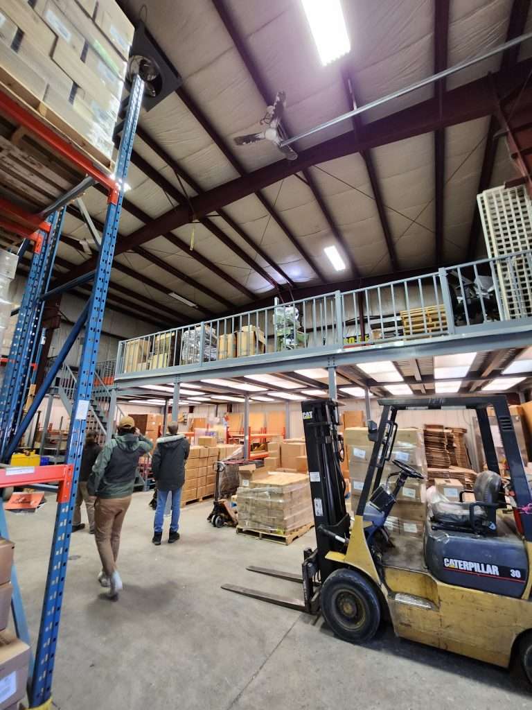

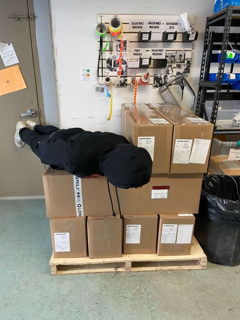


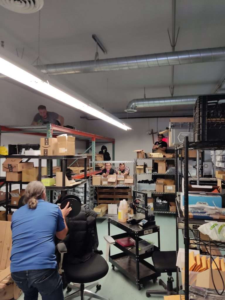
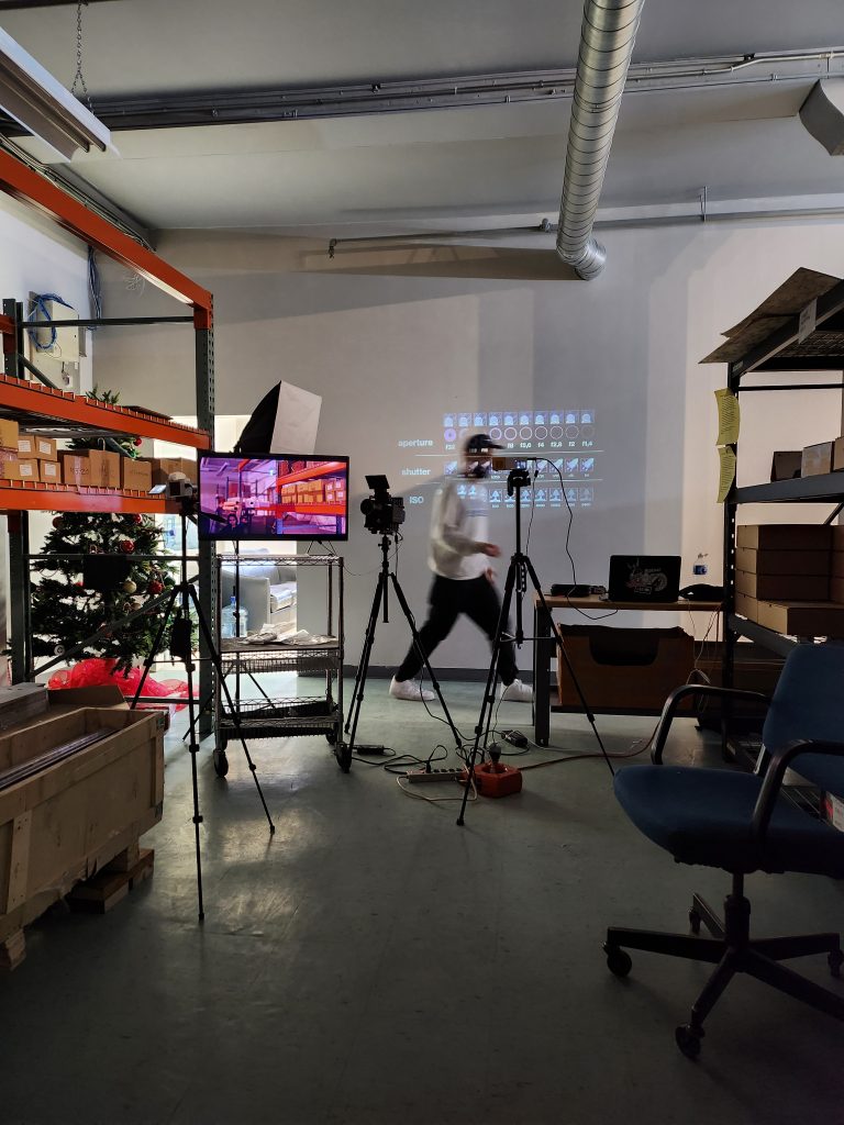 Filming bootcamp
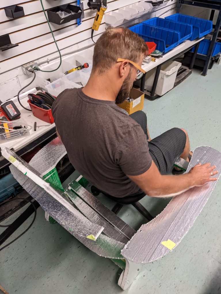
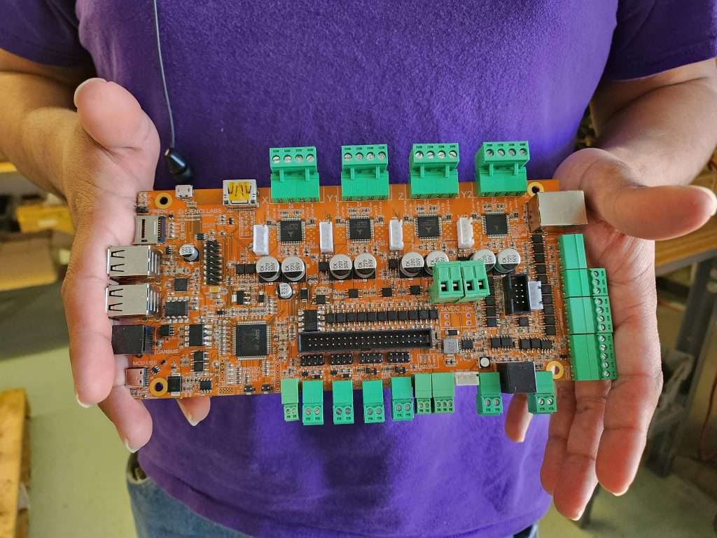
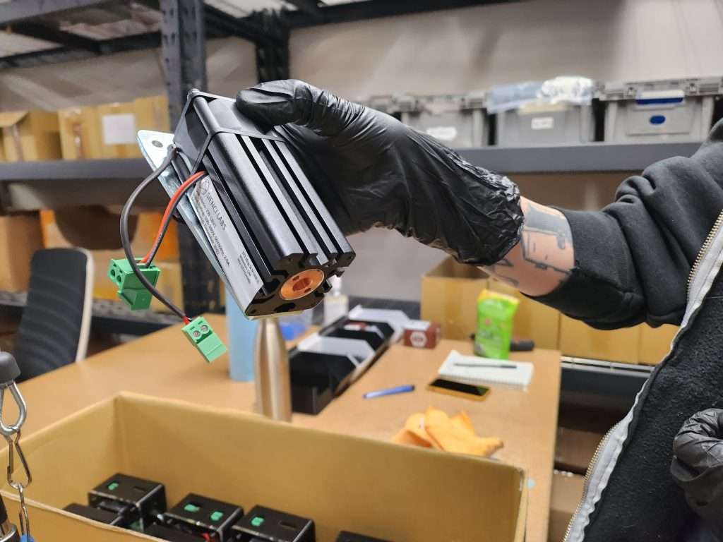
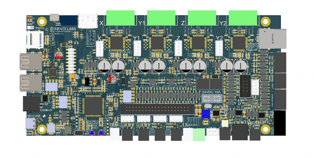 First iterations of our new control board