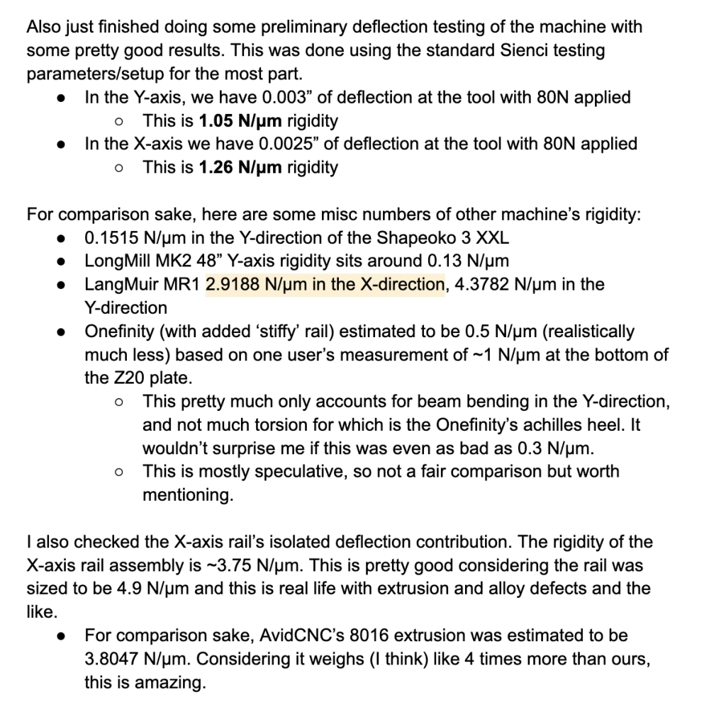
Testing the amount of deflection a machine experiences at different loads, aka the rigidity, is a good way to predict the overall performance of a CNC machine. When it comes to using a CNC machine, two primary objectives are to make the part accurately and quickly. One major contributing factor to the precision of a part has to do with how much the end mill deflects away from the programmed path. The end mill on a more rigid machine will deflect less than on a less rigid machine given the same feeds and speeds, and thus produce a part that is more accurate. Alternatively, a user can run their machine faster while still producing a part of acceptable quality on a more rigid machine.
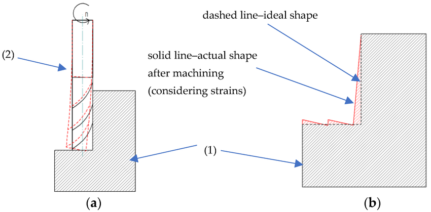
A diagram showing the effect of tool deflection and how it affects the geometry of a simple part
Perhaps a common example of how this affects a simple part of a CNCed design would be holes. Holes cut on a CNC machine tend to come out undersized, because the material on the walls of the hole push the machine and endmill towards the center.
It should be noted that deflection exists in all machines, it’s just a matter of how much. To improve tolerances, it’s common to do a “roughing” pass, which removes the bulk of the material, and then a “finishing” pass, which removes a small amount of material at the end, minimizing deflection to bring the part to final shape.
The state of the market & why we’re sharing results
As we discussed in one of our prior blog posts, there isn’t, as far as we can tell, a standardized method for testing machine deflection in the hobby CNC space.
We are able to glean general comparisons between our machines and other machines in the market by test results posted by other members of the community. As time has gone on, here are some of my personal opinions on why that is the case:
It’s hard to give context on what the rigidity numbers mean.
For most of the practical testing range, deflection is not visible to the naked eye. A lot of times, people will demonstrate standing on their machine as a demonstration of rigidity, maybe even standing on it while it’s cutting. This doesn’t really show how rigid the machine actually is, because you can’t see how much the machine is deflecting from a distance.
Additionally, just because a machine is bigger and heavier doesn’t necessarily mean that it has less deflection. Some areas of a machine’s design can affect the overall accuracy of the machine, even though it may seem insignificant at first glance. For example, from our comparisons between computer simulations and real life testing, we’re able to see that things like bolt tolerance and mechanical components shifting around under load can actually play a pretty big role in the overall deflection values. All this to say, you could have a super rigid machine, but have a weak or loose part of it, just that one part alone can have a major impact on the overall machine rigidity.
Rigidity is less important that we think it is.
Owning and using a CNC machine isn’t just about how rigid or fast it cuts. The whole experience is important, from the setup, assembly, software control, and overall reliability. For the average hobbyist, if a CNC project takes 45 minutes to cut instead of 30, does it really make a huge difference?
Return on investment in a higher degree of engineering requires high volumes to experience
Lastly, with us expecting to build a very high volume of CNC machines, a small design improvement affects a lot of users. For machines built at lower quantities or DIY machines, it’s cheaper and easier to over-engineer the machine rather than optimize it, since the cost of engineering time is higher than the cost of buying bigger or better components.
Testing process
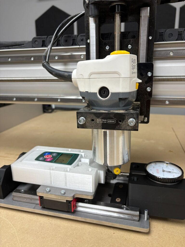
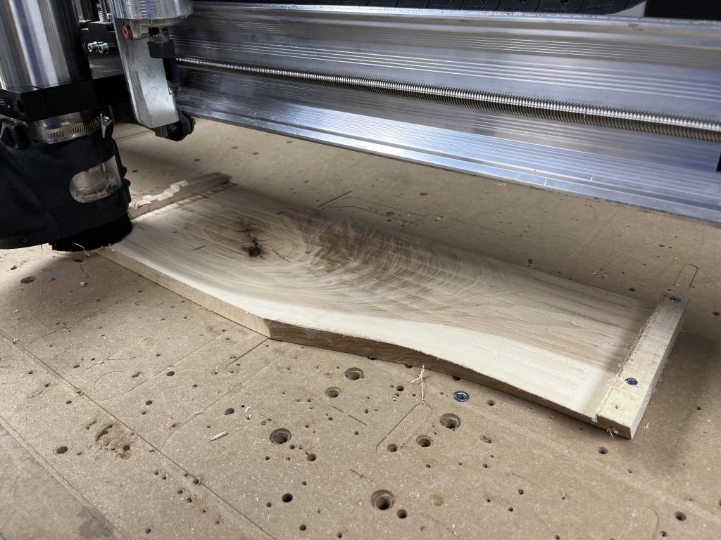
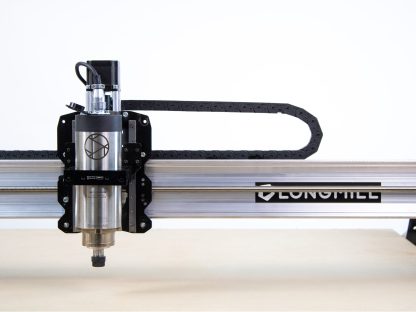
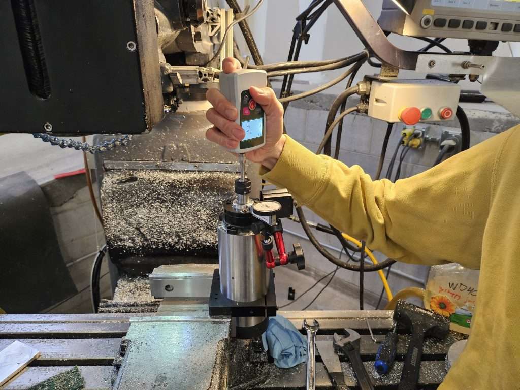
We built a simple testing jig using old prototype parts from the LongMill MK3. We have a force gauge on the moving gantry and the dial indicator on the other. When we turn the lead screw to push the force gauge against the router, it moves the dial indicator some amount. The more that the dial indicator moves, the more the machine is deflecting.
Getting straight to the results & comparisons
As we can see from our results below, we have around 65-80% improvements in rigidity between the LongMill MK2 to the LongMill MK3.
Same settings as above but with a 6.35mm step down
Same settings as above but with a 6.35mm step down
Same settings as above but with 6.35mm step down and 6.35mm step over (full slot)
Same settings as above but with 6.35mm step down and 6.35mm step over (full slot)
We will refer to some of these values in our discussion below.
Balancing machine performance and cost
Building a machine to be rigid and powerful is easy, but making a machine rigid and powerful on a budget is hard. To optimize the design of a machine, we take many factors into account.
Acceptable deflection
As my electrical engineering professor used to say, in science, 5 = 5, but in engineering, 5 = 5, plus or minus a tolerance, which is to say, whenever we cut out a part, we should expect some deviance in the size of that part, and we need to decide and understand how much deviance we can accept.
In the scope of woodworking, I believe anything under 0.005” (5 thousandths of an inch) to be “very very accurate”. For context, 0.005” is 6.25x smaller than 1/32”, or about a sheet and a half paper thick.
LongMill MK3 48×30
Force Applied (N)
Force Applied (lbs)
Positive X (thou)
Negative X (thou)
Positive Y (thou)
Negative Y (thou)
25
5.62
4.5
5
8
9
50
11.24
10
10
11
12
75
16.86
16
15
17
18
100
22.48
22
21
24
25
If we look at the range of deflection at different forces, we can determine that we should aim to keep forces to under 25N to be within the 0.005” deflection range.
Motor power
In our testing, we also measured the maximum force that the motor can apply to each axis. On the X axis (one motor), we measured the force to be around 600N, or 135lbs. On the Y axis, 256lbs.
Each motor must resist internal machine forces, such as the friction from the lead screws, bearings, and linear guides, as well as control the inertia of the machine itself. Additionally, the motor must push the end mill through the material at varying forces.
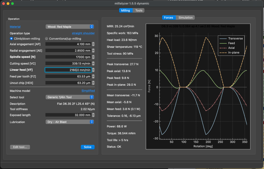
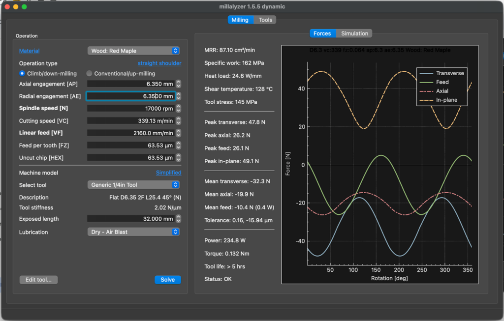
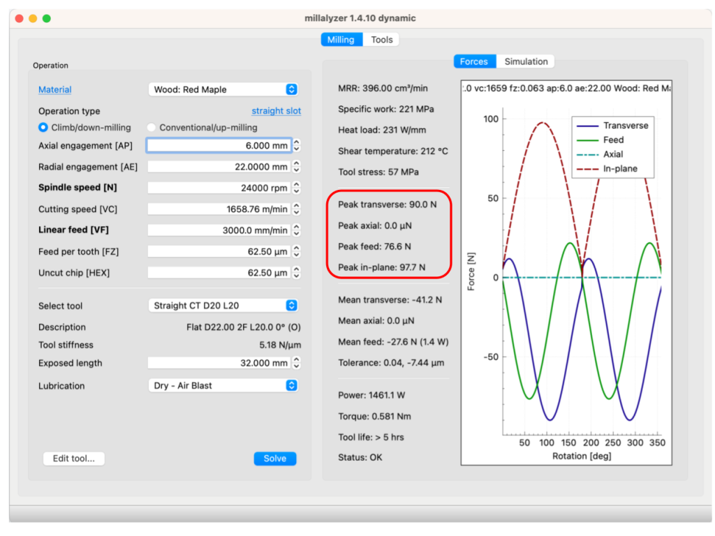
The mean and peak feed forces from Millalyser give us an idea on what those forces are (3.8N-10.4N). Based on these calculations, the motor forces are far higher than the expected loads from cutting.
A few notes:
We have 1.2NM motors on all axis, which will be the same as the ones used on the LongMill MK3 in production.
We used a 48V power supply, instead of a 24V power supply in production
Given how much more powerful the motors are, we believe that running the machines in 24V will not make a difference in overall performance. Because the 24V power supply and SLB-LITE designed specifically for the LongMill MK3 is significantly less expensive than the 48V architecture used on the AltMill, it makes sense to go down this route.
Spindle/router power
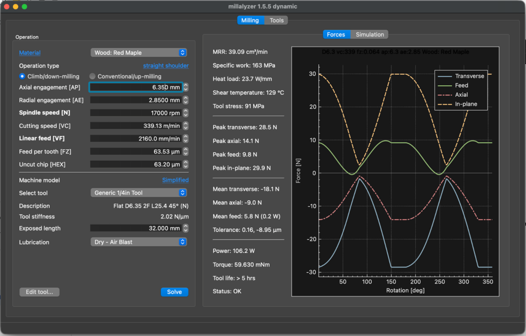
Through our AutoSpin T1 project, we did a significant amount of testing and research around spindle and router power, even going as far as building our own dynamometer to test true power output of different routers and spindles. Millalyzer also gives us an idea on the range of power draw needed from the router, ranging from 68.6 watts to 234.8 watts.
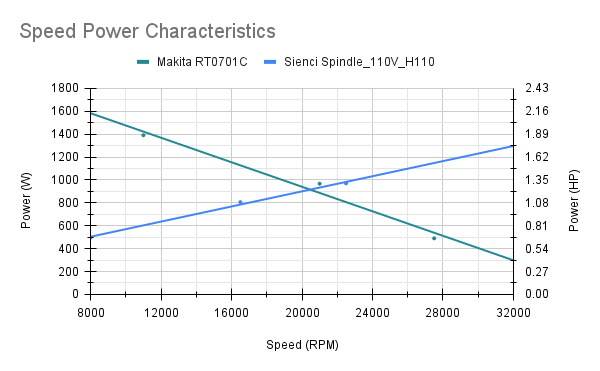
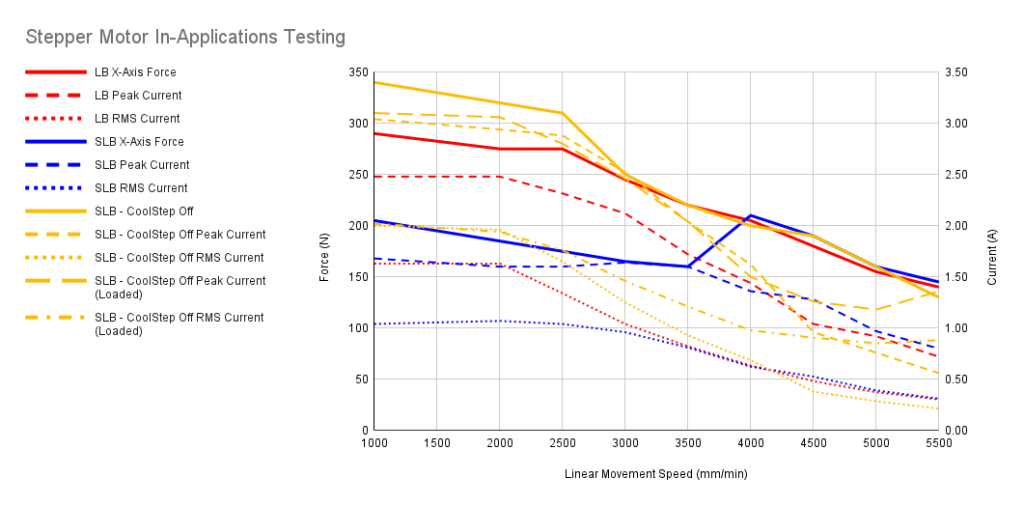
The green line shows that the Makita RT0701 can push around 1600 watts of power until dropping down to around 350 watts of power at 32,000RPM. A typical 1.5KW spindle progressively increases power output as the RPMs get higher.
We can ensure that the spindle or router used with the LongMill MK3 is capable enough by comparing the estimated power draw from Millalyser to our measured output line. In either case, both the Makita RT0701 or 1.5KW spindle is more than capable of producing enough power.
Our LongMill 1.5KW spindle kit costs around $650USD versus AutoSpin T1 is around $150USD, which is a 4x difference. Users can use either option, but we believe that the AutoSpin T1 is adequate for this application with the added benefit of the lower cost.
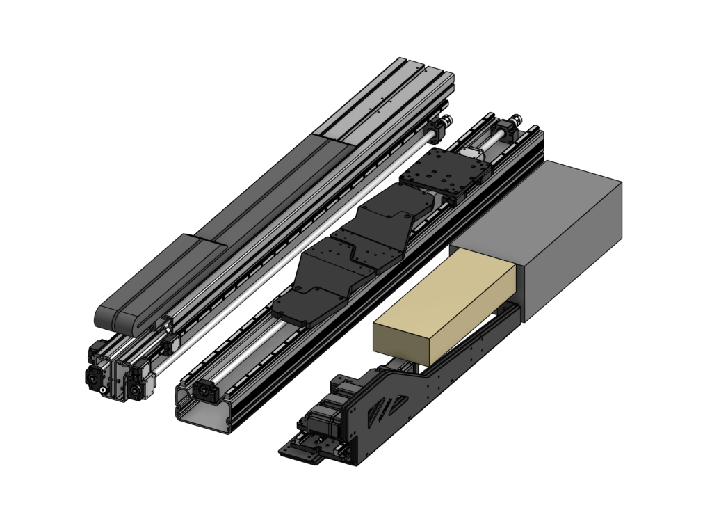
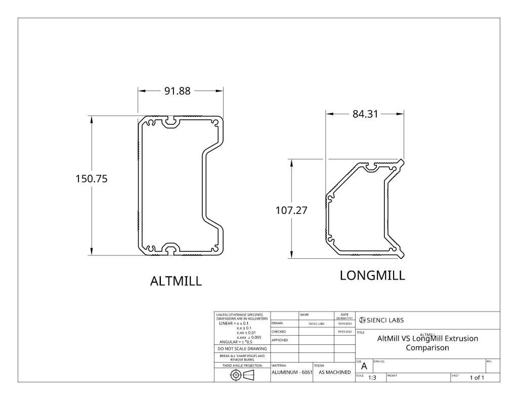
AltMill vs LongMill MK3 comparison
As it stands, the AltMill is approximately 2-4x more rigid than the LongMill. This is largely due to:
Thicker and heavier structure on the AltMill
Higher mass of the machine on the AltMill
If performance and rigidity is very important to you, the AltMill does provide much more in that way.
There are some practical considerations to make when it comes to actual differences in cutting, such as:
This is something I learned people call the “pucker-factor”, which is that people may not be so inclined to push their machine as hard as they can because of a lack of confidence.
Tools have a limit to how hard they can cut because they can deflect and break as well
Overall, I expect the practical cutting performance of the AltMill to be around 2x of the LongMill MK3.
If you’re cross shopping between the LongMill and AltMill, here are the prices to consider:
LongMill 30×30 ~$1390USD or $1870CAD
LongMill 48×30 ~ $1790USD or $2410CAD
AltMill 2×4 ~ $2790USD or $3890CAD
AltMill 4×4 ~ $3160USD or $4290CAD
…so between LongMill MK3 48×30 vs AltMill 2×4, which I think is the closest comparison based on working area, the price difference is around $1000USD, or comparing the 4×4, $1370USD.
We should also note that the AltMill also requires a spindle, larger tooling, and higher power dust collection to get the maximum performance, which can increase the cost difference when comparing between total setup costs.
Conclusions
With improvements to the machine rigidity and motor power, we expect users to be able to cut much faster and reliably compared to the LongMil MK1 and MK2. A significant amount of work and consideration has been made to improve performance overall while keeping the price the same as the older generation.
While this article only covered testing around rigidity, make sure to stay tuned on discussions of other improvements for the LongMill MK3, including easier assembly, maintenance, and electronics as well!
We hope you enjoyed this report on the LongMill MK3 design and performance!
It’s been a short 10 months since we first launched the AltMill.
We’ve learned a lot with our first batches of the AltMill and we’ve combined all those things into improvements to our latest version. We’re now excited to share our second iteration of the MK2, which bring improvements to the quality, ease of construction, and quality of life, as well as preparing for new iterations and development for the Sm-AltMill and 4×8 machines in the future.
The MK2 refers to the platform change, which means that any machine with the new design changes are part of the MK2 family, which means that the AltMill 2×4 is also a MK2 machine.
If you’re looking for more information about the AltMill MK2 2×4, please check out this other blog post.
AltMill MK2AltMill MK1
Production changes and challenges
AltMill lead times have continued to be long since the first launch of the machine. While our production rate has continued to increase over time, decreasing lead times have also coincided with increased demand, due to the growing public knowledge and interest of the AltMill. We are working on a number of things to decrease lead times and our goal is to eventually have units ready to ship in 1-2 weeks on average.
Batch sizes
To mitigate the risk of quality and technical issues in the shipping of our first batches, we’ve kept batch sizes relatively low, with Batch 1 being 50 units, Batch 2 being 200 units, and Batch 3 being 250 units. Batch 4, which we are currently in, is something of a split batch of 500 units. I am calling it a “split batch” because some components have been ordered and produced in a batch of 500 while some have been ordered in a batch of 250, based on cost, size, and our confidence in the part quality. Additionally, we’ve been working to diversify our supplier portfolio, so that we can split up parts from the same batch across two or more suppliers, allowing us to decrease lead times.
Supplier diversification
As our part complexity and quantity grow, we’ve worked to diversify our portfolio of producers and manufacturers. The first is to distribute work to decrease lead times. By using more than one manufacturer to produce the same component, we can ensure that if one manufacturer has issues or is delayed, we still have a second source for the products. Plus, if parts take a long time to make, having a smaller batch to produce can reduce the total production time.
Second, we’ve been working with different manufacturers to understand their strengths and distribute work based on their competencies. We found that some manufacturers may be proficient in extrusion production but not in machined components. Traditionally, it was easier to aggregate production to reduce the number of suppliers and logistical overhead, but at this point, we’re at the scale where it makes more sense to have manufacturers focus on their core competencies to have the best quality possible.
Production space changes
Since moving into our new space in north Waterloo in November 2023, our space has adapted significantly. We’ve implemented new racking and equipment to increase the storage capacity of our production area. However, as we increase our batch sizes, our demand for space will increase as well. At this moment, our team is working on expanding the production area with potentially taking over more of our current building, as well as looking into a second space for warehousing.
Design changes and challenges
When working on the first batch of AltMills, we encountered a number of problems, some we were expecting and some we weren’t. Much of MK2 development is to address and improve the overall manufacturability and ease of customer assembly.
Extrusion
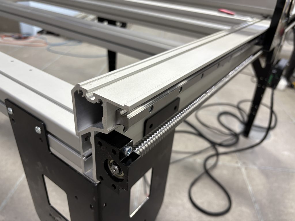
As we found when we first developed extrusions for the LongMill MK2, we knew that ensuring the flatness and straightness of the new extrusions were going to be critical in ensuring the precision of the machine. With the AltMill, with larger rails and the addition of linear guides, tolerancing was going to be an even more important part of the process.
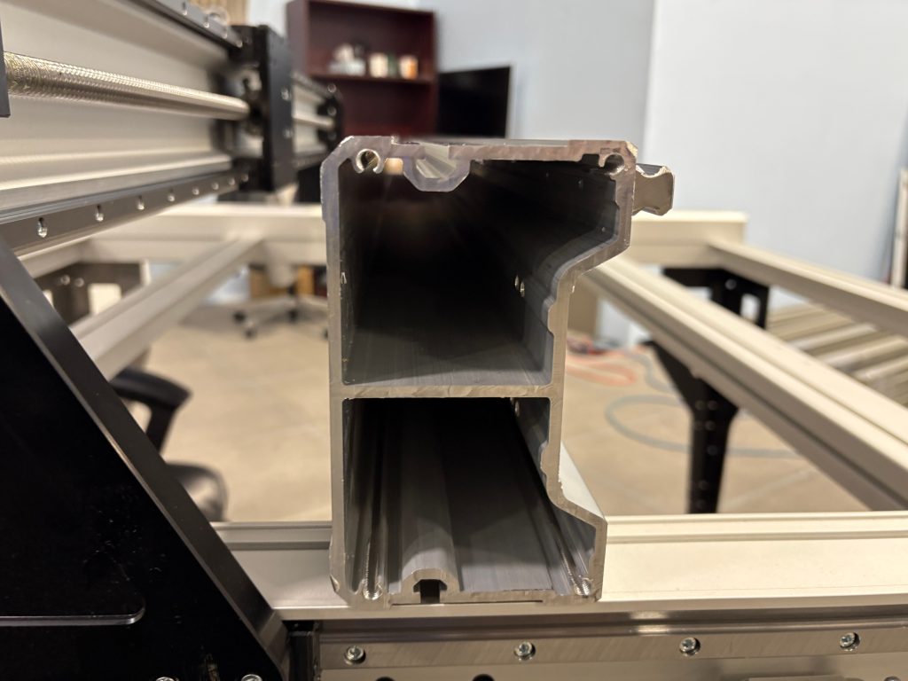
Having material furthest from the center of the axis of rotation or flex offers the most rigidity in a structure. This is why in the initial design, the inside of the rail did not have any cross bracing. This might be counter intuitive, but actually is the most optimal way to design the rail. However, what we learned was that having some sort of cross-bracing would improve the straightness of the rail in production. While there is a small tradeoff in weight and potential performance, these differences are negligible for the added benefit of having higher production yield.
The original design and the current design both use machined surfaces to ensure that even with some deviation in the straightness and flatness of the rail, the linear motion would still mount without binding, but we found that in extreme circumstances, the rail would be so bent that the center of the rail wouldn’t get machined at all. These rails would need to either be re-machined or scrapped.
Another unexpected small benefit was the fact that the cross-brace increased the resonant frequency of the system itself so that the machine “rings” less.
Inside of the Y railInside of the X rail
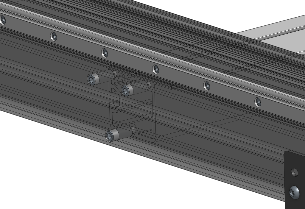
Additionally, to aid with assembly, the Y-rails come with a small extruded “ledge” that helps keep the crossbeams supported and straight. This also improves the speed of assembly as the crossbeams can be held in place by the ledge while being bolted together, and the table does not need to be flipped twice during assembly to mount the table legs.
MK2 designMK1 design
Crossbeams also now mount using a custom tall-head screw, making it impossible to drop into the rail, and improving accessibility of the screw head for easier assembly.
Custom tall-head crossbeam screws
To add one more change to the Y-axis extrusion design is the integrated dust cover for the ball screw, instead of the stainless steel covers used on the MK1, which serve the same purpose, but reduce the assembly time and total part count. The addition of the ledge for the drag chain also helps keep it aligned during use. This recessed area also exists on the X-axis rail to help align the drag chain as well.
MK2 dust coverMK1 dust cover
A last subtle difference in the MK2 extrusions is the consistent use of a more fine bead blasted and anodized finish on all extrusions including the crossbeams. This is more costly than the unanodized crossbeams used in the MK1 AltMill, but greatly enhances overall polish of the machine – even if these parts get hidden by the wasteboard.
Machining
One aspect of the manufacturing that proved to be a larger headache than expected was with the threading of the extrusion, notably, the M4s used with the linear guides and end tapping with the crossbeams. With the manufacturing of the LongMill MK2, we ended up developing a system to tap the extrusions in-house, especially since we had also started cutting rails for each of the various sizes for the LongMill as well. However, given the larger number of tapped holes, we had to bring the tapping out of house.
We found that some of the tapped holes had weak threads, causing them to strip during the assembly of the linear guides or when installing the crossbeams.
We’ve improved the quality control and documentation so that our manufacturers are able to catch poor threading, however, we recognize that ensuring proper threading would always be a part of the manufacturing process, so we are working towards bringing the machining and tapping in-house as well. As a redundancy, threaded sections of all rails have been strategically thickened for reducing the likelihood of strip-out when over-torqued.
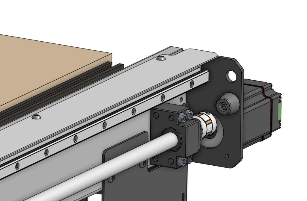
Wire management
One of the common criticisms of the AltMill was its lack of well-thought-out wire management. This means that users would end up with a pile of wires at the SLB. Since all of the motor cables are the same length, depending on how far the motor is from the controller, the user would end up with varying amounts of excess cable. Additionally having bundles of long cables going to each corner of the machine can be unwieldy and prone to assembly error.
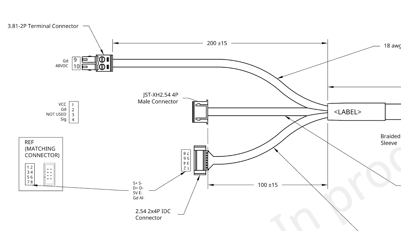
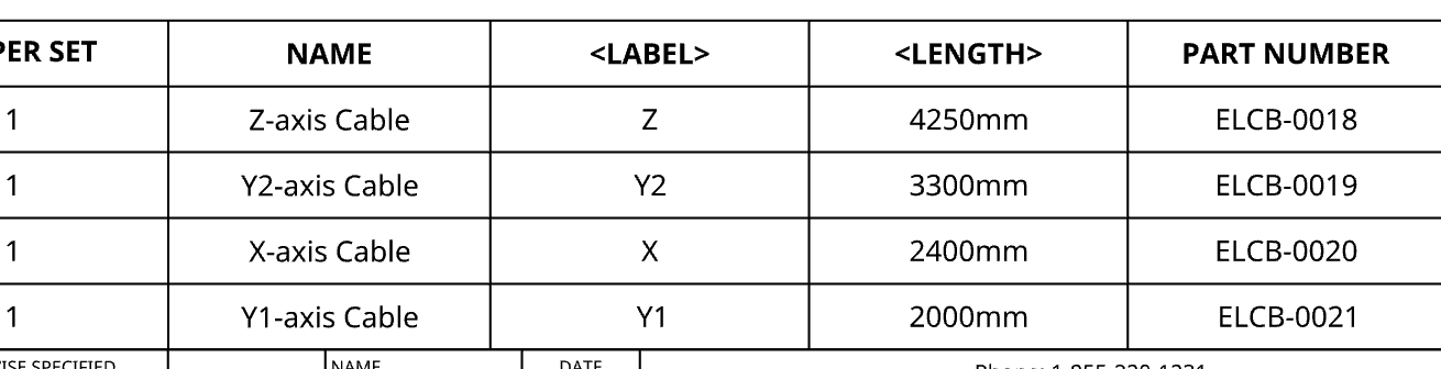
The MK2 implements new wiring that comes with pre-determined lengths and is pre-bundled for each axis. We’ve decided that although the packaging and supply chain may be a little more complicated on our end, ultimately, the improved tidiness and ease and speed of assembly would be worth it. This means that each cable is labelled and comes to an exact length to reach the controller. This also makes it easier to catch errors in assembly as wiring plugged into the wrong location would also be more apparent due to different wire lengths.
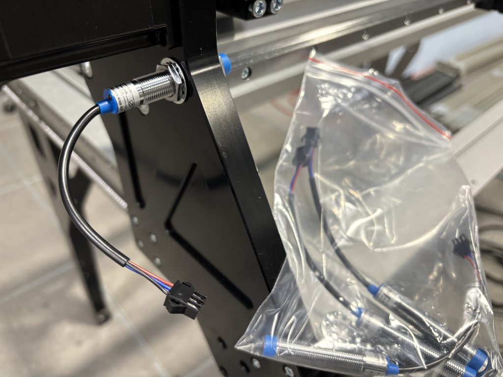
Additionally, each cable harness now includes an integrated limit switch cable, meaning less individual cables to route during assembly, as well as an easier time to identify where each limit switch plugs in.
Limit switches now connect to the integrated wire harness using a small locking connector. This makes installation of the switches and wiring a bit easier, as well as allows for easy replacement of limit switches if needed.
New ‘pigtail’ inductive sensors
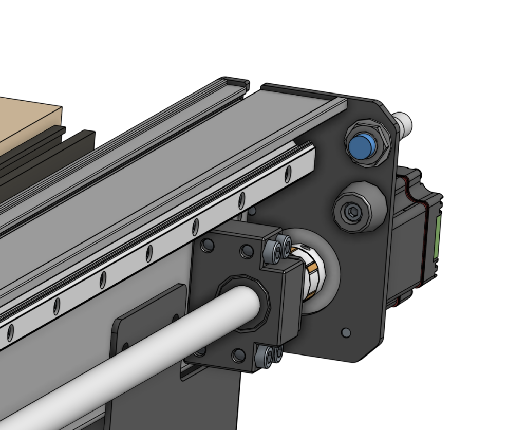
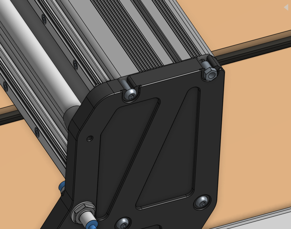
This work is also done in conjunction with adjustments to the front and back motor plates used on the Y-axis to utilize the inside of the extrusion to hide and protect the wiring. Additionally, we’ve made some changes to the SLB-EXT controller case to make wire management easier and cleaner.*
Y-axis end plate allowing for wires to be passed through the inside of the extrusion to the rear of the machine
Please note that changes to the SLB-EXT are expected to come near the middle of the AltMill MK2 batch. Both controllers are the same and are cross-compatible with each other.
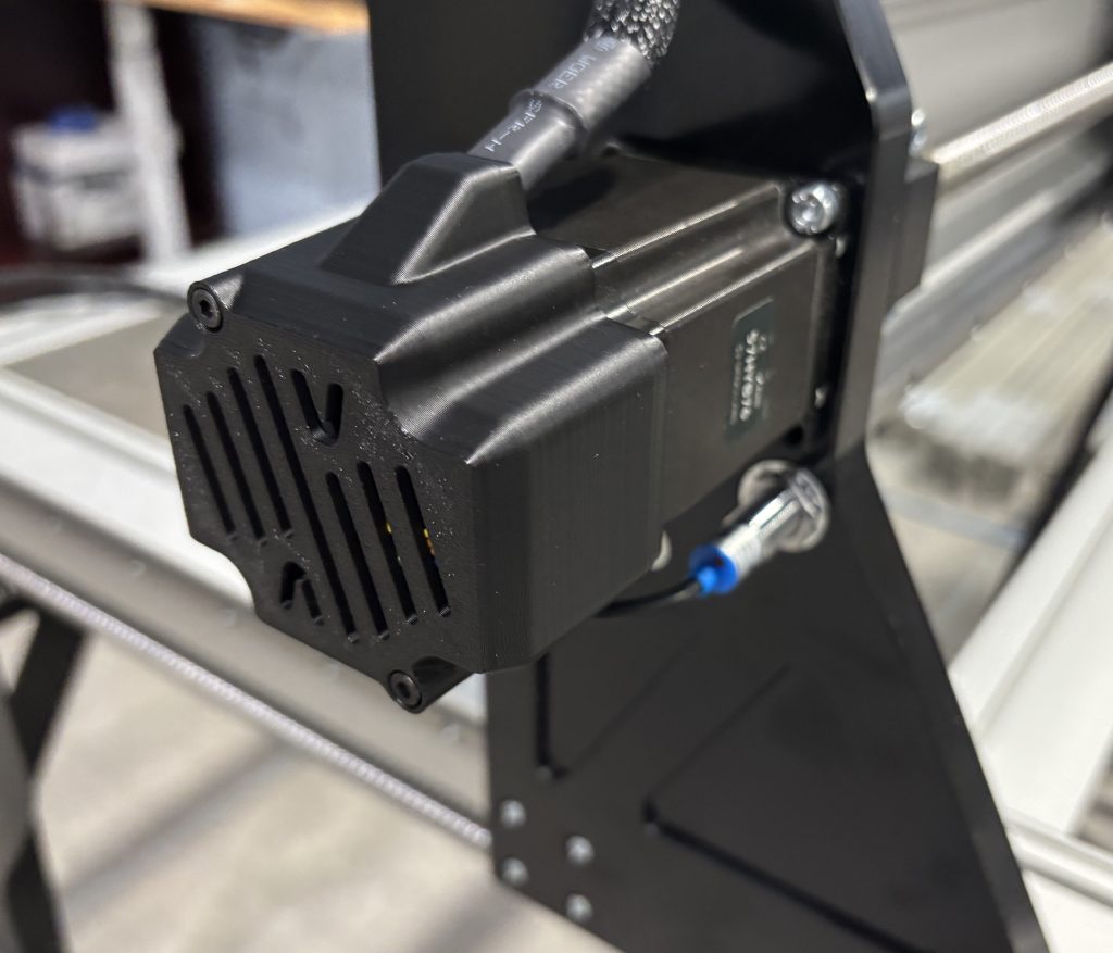
Motor covers
On the AltMill MK1, motor cables exit from the rear of the motor and curve backwards towards where the cables are routed from. In some instances, this could cause connectors to fall out, or individual cables to break in extreme cases. Early on, right after launching, the individual cable crimps were changed to prevent these individual cables from breaking or coming out, but it was still possible to have connectors become come loose from their socket.
On the AltMill MK2, molded plastic motor covers are used at all four motors to: -Mechanically secure motor connectors from coming loose -Provide strain relief for each cable harness and redirect this towards its cable routing path -Provide protection of the motor and connectors without impeding any heat dissipation of the motor.
Molded plastic motor cover
Backwards compatibility to AltMill MK1
It’s important to state here that the updates and changes made to the AltMill are primarily for ease of manufacturing and assembly. If you already have a AltMill MK1, it’s unlikely you’ll need or want to change or upgrade your machine to a MK2. Many if not most components are still cross compatible, which means that some replacement parts that will be available for the MK2 will also work with the MK1.
If I have an AltMill MK1, can I update it to the MK2?
If you already have an AltMill MK1, most of the parts are backwards compatible with the MK2. However, most of the updates made are to improve the assembly and manufacturability of the machine, so if your machine has already been assembled, there is little to no practical advantage to updating your machine from a AltMill MK1 to a MK2.
We will not have parts immediately available for purchase, but we are working stocking and uploading parts that can be used between the two machines.
Additionally, if you already have a MK1 on order and would like to change your order to a MK2, please contact us. Please note that changing your order from a MK1 to a MK2 may delay the shipping of your order, plus have a price difference, as we will complete shipping of AltMill MK1 before AltMill MK2.
Electronics and software remain the same and will continue to be updated in line with the MK2. Resources and instructions, and tutorials will still continue to be relevant to both versions of the machine.
If I have an AltMill 2×4, can I update it to a 4×4?
Theoretically yes. To update it to a 4×4 size, you’ll need to replace the Y-axis rails, ball screws, motor harnesses and add an additional 2 crossbeams. It is our plan to have, as we currently do for the LongMill, parts available for purchase in our store for modifications and changes. However, the cost of the conversion on an individual basis may be high, and we don’t have a specific timeline or roadmap for a dedicated kit or instructions, so we strongly recommend ordering and committing to the size that you plan to use for the long term.
Pricing
Base price for AltMill 4×4 goes from $3990CAD to $4290CAD or $2950USD to $3160USD, ($300CAD difference or $210USD difference).
Base price for AltMill 2×4 to be $3890CAD or $2790USD.
Pricing for spindles and other accessories remains the same.
We are adjusting pricing for the AltMill to reflect some of the changes and improvements we’re making to the MK2 and better reflect our current costs for production.
The AltMill 4×4 MK2 and AltMill 2×4 will be available to order with updated pricing on Jan 29th, 2025 11AM EST. On Jan 29th, only the AltMill MK2 versions will be available for order.
Please note that this is expected pricing but pricing may change.
Hey everyone. I’m excited to share more details about the AltMill 2×4 (the AltMill with a 4×2 ft working area) and other sizes coming soon. We are expecting the launch of the AltMill 2×4 A few months ago, Ben took some time to put together a version of the AltMill with a 2×4 foot (approximate) working area using spare and scrap parts left over from production and posted a video about it. Since then we had a lot of interest in smaller versions of the AltMill.
Availability to order the AltMill 2×4 is tentatively scheduled for Jan 29, 2025 and expect to ship at the end of March. The AltMill MK2 2×4 will be available for order on Jan 29, 2025 at 11AM EST.
AltMill MK2 2×4 (machine only) to be $3890CAD or $2790USD.Spindle and Dust Shoe Kit pricing at $690CAD/$515USD
Since showing off this version of the AltMill, the response from the community has been overwhelming, encouraging us to develop and work on exploring different sizes of the AltMill.
Why different sizes?
After building and testing the AltMill, it became clear to us that the design and platform had a lot of potential to be used in a lot of different applications. The main innovations of the AltMill come from optimizing the design for rigidity while making it as easy and efficient to assemble at scale, which translates to different sizes as well.
As it stands, we believe we haven’t fully unlocked the power of the AltMill. We still have a lot of development and progress to make with:
Higher power spindle options
Automatic tool changers
Coolant options
Advanced clamping, vices, and other hold-down methods
The main goal for building all the different sizes, ultimately, is to serve a larger audience who want to use their machines for different applications beyond just the typical woodworking projects that our machines and industry have been focusing on such as:
Aluminum milling
Steel milling
Plasma cutting
Fiber laser cutting
Automating tasks such as drilling and tapping
Fundamentally, the AltMill serves as a platform for CNCs designed for many different uses and leverages development across all of the different platforms to trickle through the whole ecosystem.
Who is it for (AltMill 2×4 and smaller)?
We’re not a 100% sure yet but here’s some of our thoughts.
People who want to do small-scale production for a specific part:
Although a larger machine is more versatile, for users who want to have a machine suitable for machining specific products and parts, a machine just large enough for that specific part may be the best option, especially in space-constrained locations. For example, the AltMill could be jigged up to make guitars in a production setting, as the workspace is large enough for a full neck and body.
Another advantage of the AltMill is that businesses that need to do production can in theory order and have a machine shipped to them directly on short notice (or at least once we finish optimizing our production), allowing them to scale production quickly when they need additional machines.
Education or use in an institution:
We’ve also gotten interest from people who want to use CNC for teaching or institutional use, where the focus is less on producing parts and more on learning and testing. This could be in CNC software companies testing their CAM software or colleges that need lower-cost CNC machines that are robust enough for students to use while fitting in smaller classrooms.
The AltMill works on the same core technology as any industrial CNC machine, which means that it can provide an entry into CNCing without the risks and costs which come with industrial machines. The open-source nature of our designs and company also allows for institutions to adapt their machines to their needs as well.
For fun:
While AltMills are not cheap, they do come in at a price point that makes it accessible to most dedicated hobbyists. We expect pricing for all versions of AltMills to be around the current price of our 4×4, with variations based on size and configuration. This means that users may choose to buy a CNC machine just for the heck of it.
Sm-AltMill (Small AltMill)
Concepts of a smaller, metal milling-focused CNC internally called the “YesHappy” or “Sm-AltMill” have been tossed around in the shop for some time. From our perspective, we feel there’s a gap in the industry for a small, benchtop-sized CNC machine for milling aluminum and steel. While there are some options in the $2000-5000 range, we feel they are either underpowered and only good for small parts, and consumers need to spend around $10,000-$30,000 to purchase a smaller milling CNC or VMC.
Prototype Sm-AltMill
Here’s a list of machines that we found that are sort of in this space.
Machine
Price (CAD)
Cutting Area(in)
Spindle Power(kW)
Motion System
4 Axis Compatible From Factory
Makera Carvera
7800
0.2
Slide Bearing
Yes
Shariff DMC
4550
2.2
No
Sainsmart Gemnmtsu
1945
0.4
Delrin Wheels
No
Yorahome Crossriver 6060
4107
24x24x5.8
0.5
Linear Guide
No
Carbide 3D Nomad
3640
8x8x3
0.12
Slide Bearing
No
Source Rabbit Quantum
12800
13x13x4
1.4
Linear Guide
Yes
Langmuir MR-1
6500
23x22x6
2.5
Linear Guide
No
Kitmill AST
11000
8x5x4
0.1
Linear Guide
No
Stepcraft-3 D420
3000
12x16x5
1
No
Coast Runner
No
Onefinity Machinist
2400
16x16x5
Makita
35mm Rail
Yes
Bantam Tools
11000
7x9x3
Linear Guide
Yes
So where do we land for this? Here are some considerations:
With our software and hardware stack, we can support advanced functionality such as 4th axis support, coolant control, closed-loop steppers, and more without additional development, since functionality has already been worked on and developed for AltMill and LongMill already.
Since we are already assembling and building AltMill at volume, we can take advantage of economies of scale for many of the parts used in the other-size machines.
The rigidity and accuracy of the AltMill generally exceed the majority of the machines on this list and can be optimized further. Based on our testing, we’re able to reach material removal rates on the regular AltMill 48×48 compared to the highest-powered machines in this list, and we expect that a smaller version of the machine would increase the overall rigidity to continue to meet or exceed performance across the board.
There are a couple of things that we’re working on now including:
Reaching out to people in the machining community to get their thoughts on this sort of product
Figuring out the balance between cost, features, and performance
Playing around with different add-ons such as ATC and coolant
Building a small batch of beta units
Testing metal-specific tooling
Larger machines (AltMill 4×8)
On the other hand, we’ve also been getting a ton of interest in a 4x8ft version of the AltMill. Our team has been considering this as well, and identified two main short-term challenges and one main long-term challenge in bringing this to market.
First is the packaging. One of the main advantages we have is being able to pack and ship everything through a courier like UPS. This avoids the need to deal with complicated freighting and equipment needed to load and move large CNC machines. However, using a courier for very large shipments can be expensive and sometimes not possible depending on the size and weight of the order. Additionally, shipping items through couriers run a higher risk for damage, as shipments go through many hands and get stacked and piled on top of other shipments.
We believe that using the courier method does make things more accessible since we can deliver CNC machines to residential locations. However, the larger and heavier the machines become, the more difficult it is to work around the limitations. That being said, we’ve seen lots of examples of this, and we believe, we can sort out something that works.
The second challenge is with power transmission. Since the Y-axis needs to get longer, it also means that the Y-axis ball screws will become more prone to whip if we keep the same design. This can be mitigated with a number of options, such as using rack and pinion, larger ball screws, or something else, but this means that we’ll have to engineer another way to move compared to the existing solution. Of course, designs and solutions already exist, and we believe that we’ll be able to figure something out in this area too.
Lastly, the other, perhaps long-term challenge comes down to our company scale. Larger machines take up more space, and although we just moved into a larger office about a year ago, we’d be looking at moving into an even larger space as soon as we start production for 4×8 ft CNCs. Additionally, and perhaps the even bigger challenge, is hiring and onboarding more team members to support the new product.
With that in mind, we do believe that there is a space in the market for an AltMill 4×8, and we have been chipping away at the design and logistics to eventually bring it to market. Make sure to stay tuned for new updates.
Pricing
There are some fixed costs associated with all versions of the AltMill, such as:
SLB-EXT controller
Spindle (although the specific version may vary depending on the use of the machine)
Closed-loop stepper motors
Gantries (although there may be variations for machines designed for milling metals to accommodate vices and additional workholding)
Couplers, bearing blocks, and other assorted hardware
On the other hand, costs for items that are size-dependent include:
Linear guides
Rails
Packaging and shipping
We predict that material costs for smaller machines will be relatively close to the 48×48 AltMill. Some additional costs include:
Resource and support costs for each variation of the machine
Unique packaging and assembly costs
Development costs
Additional machine-specific accessories such as coolant support and vices
All in all, we don’t expect pricing to be dramatically different compared to the current AltMill, which we believe is well-priced on its own. Customers should expect pricing for the AltMill 2×4 to be similar to the current price for an AltMill 4×4. Finalized pricing will be available near or at launch.
Next steps
Production for more AltMill rails is now in production, which includes approximately additional rails needed to build around 100 AltMill 2×4 We’re expecting them to arrive around the end of February, which means we’ll have the first parts needed to start building around 100 units.
Our team is currently working on media and marketing materials to prepare for the launch of AltMill 2×4 on the store, which is tentatively scheduled for Jan 29th.
We expect AltMill 2×4 to start shipping in March.
Additionally, we are in production for an additional 25 sets of rails and parts for a 16×16 inch working area machine (Sm-AltMill), which will be focused on metal milling. We do not have a specific launch plan for this yet, but we are collecting feedback and doing market research to understand how we want to configure the design for this. We will be reaching out directly to potential users for sales of the first batch, so if you’re interested, make sure to fill out the survey.
We are expecting the Sm-AltMill to be sold and built on an individual basis and customized and tested for different uses, which means that they will not be publicly available for sale at this time.
FAQ
Is there going to be a way to upgrade from a 2×4 to a 4×4?
It is likely we will have a kit available, but we likely will need a few months after the launch to sort out the product and resources for size changes, so we recommend picking the size you’ll be committing to up front for now.
What is the footprint of the AltMill 2×4?
The footprint is approximately 52in wide and 39in deep. From the bottom of the foot to the top of the motor, the height is approximately 56in.
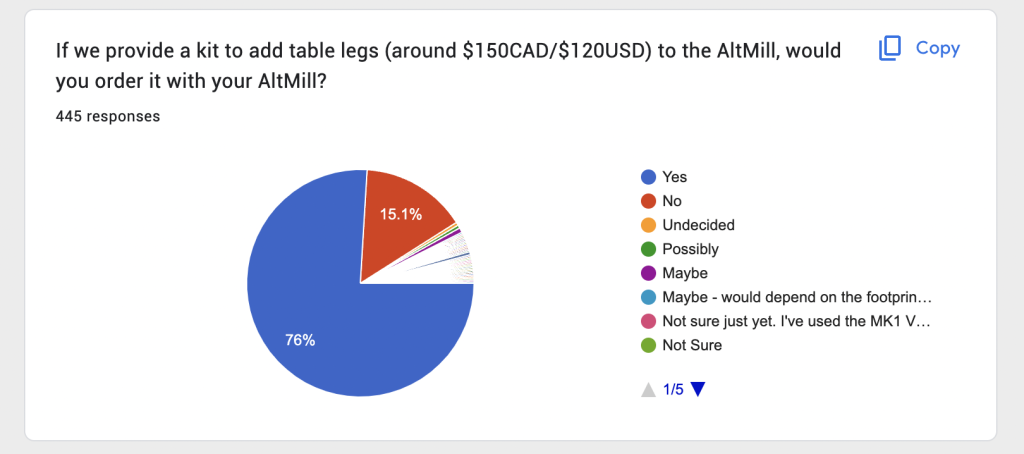
Do the legs come with the AltMill 2×4?
Just like the AltMill 4×4, the AltMill 2×4 comes with steel legs.
What accessories work with the AltMill 2×4?
Any accessory that works with the 4×4 will work on the 2×4. This includes any spindles, gControl panel computer, Vortex Rotary axis, and more. We expect that future add-ons and features designed and developed for 4×4 will work on 2×4 as well.
What is the price for an AltMill 2×4?
Official pricing has not been established, but users should expect pricing to be similar but slightly less than a 4×4.
When are AltMill 2×4 expected to ship?
2×4 machines are expected to start shipping in March 2025.
Where can I buy an AltMill 2×4?
Pre-orders will be available on our website at the end of January.
Will there be any other sizes of the AltMill?
Besides the Sm-AltMill with a working area of approximately 16×16 inches, we don’t have any immediate plans for other sizes at the moment.
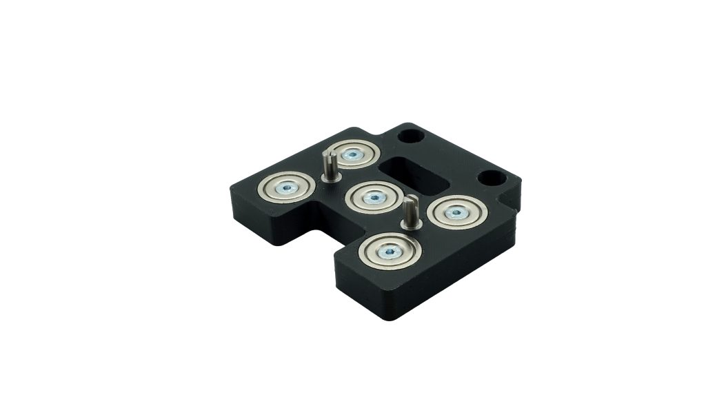
The LaserBeam Magnetic Mount is now available for purchase! Streamline your setup by eliminating the tedious bolting process. Once installed, simply snap your laser on and off for quick and easy adjustments. Crafted with durable, high-strength magnets, this mount ensures exceptional stability and rigidity, delivering precise and clean results within recommended speed ranges. Upgrade your experience today!
Feel free to explore all of our other resources for updated information on LaserBeam compatibility with the ever-expanding line of Sienci Labs products.
Hey everyone, I’m excited to finally share details and launch the gControl Panel Computer. We’ve been running several of them in the shop and they’ve been incredibly handy and versatile in running our CNC machines, and I’m sure you’ll find that too.
Here at Sienci Labs, one of our main goals is to make our machines as reliable as possible. This means designing, developing, and testing every aspect of our product. The development of the SuperLongBoard was one of those initiatives to improve the electronics side of our machines.
While on the original roadmap, we had planned to integrate a computer directly onto the SuperLongBoard, which would allow users to run gSender and control their machine in a single board, we found that doing things this way would greatly complicate the process and cause other potential issues, so we decided to split the development into two parts, the board, and the computer.
For those who might not have been following Andy’s production updates, we’d originally envisioned the SLB as being a system of two different parts working together. The first being the board itself, containing all of the core CNC functionality controlling motors and handling g-code, and second being an optional onboard compute module that would act to replace a computer or laptop and instead be integrated. Users could connect a keyboard, mouse, and monitor to control all functions of the machine directly through the SLB. This was very exciting to us given the considerably low price of the compute module over a computer, around $40-80 dollars plus the cost of the monitor, keyboard, and mouse, as well as the extra speed, user experience, and reliability of an onboard system.
In our extended tests with this idea in mind, we weren’t finding the success we’d hoped in creating a seamless user experience with this solution. Despite trying many Linux kernels, drivers, GPU acceleration, and bringing many more efficiencies to gSender, the Broadcom and Rockwell-based processors used on smaller compute modules were not powerful enough to accommodate the visualization of g-code directly onboard. This also meant they didn’t have extra headroom if in the future we wanted to implement other features such as having a camera monitoring system or other sensor inputs. With many months delay trying to chip away at a resolution we decided to split the development of SLB back into its two parts; prioritize improving the baseline machine performance first so CNCers don’t have to wait any longer for the SLB to make better machines, and strip out all the on-board connectors and switch to a higher-power off-board solution that we’ll implement at a later stage. This will mean anyone could still upgrade at a later date. Higher-power Fanless PCs will cost more, from our initial budget of around $80CAD/60USD for the compute module, to somewhere around $100-$200USD depending on the specs and configuration, but would ensure a smooth and seamless experience as well as provide headroom for future applications.
To summarize, we decided to take the concept of the onboard computer and divide and conquer on it at a later date. It would’ve been really cool to have a fully integrated system but it kept pushing our board delivery back further and we felt it would benefit everyone if we just pushed ahead on the other features that will all still bring great benefit to the CNC experience. This means that users will still need to connect their computers to the board to control their machines when the first batch of SLBs release, but should still see drastic improvement.
I’m happy to say that we’ve seen significant improvements to the overall reliability of people’s CNC machines. However, the computer side of things is still an area we need to tackle.
Over the past year, we’ve experimented with different computer hardware options, from mini computers from Amazon, to different compute modules, Raspberry Pi’s. Here are some of the hurdles:
Some items, like Raspberry Pi were often out of stock and hard to buy in bulk. This created concerns around us being able to get the number we’d want in the long run.
Lower power hardware, such as x86, ROCKCHIP, and Raspberry Pi did not have the graphics support or processing power to handle the graphics visualization for gSender. While the hardware would be less expensive, we would need to strip out features and spend more in development for compatibility.
Integrating a computer meant no upgradability in the future. If one of the parts breaks, you’d have to replace the whole board.
Going for an industrial panel computer felt like the no-brainer choice. Some of the pros being:
They are readily available from a number of manufacturers and can be configured in almost an infinite number of ways.
Would require no changes to gSender to run.
Given that they incorporate the screen and touch interface, would cost about the same as buying all the parts separate
Allow more features such as networking, SSH, and even be used to check your email
At the end of the day, I don’t think there’s a difference in whether the computer is on board the controller or off the board in terms of usability. I call it the “wizard behind the curtain”. If the use of the machine is the same, does it matter?
What is gControl Panel Computer?
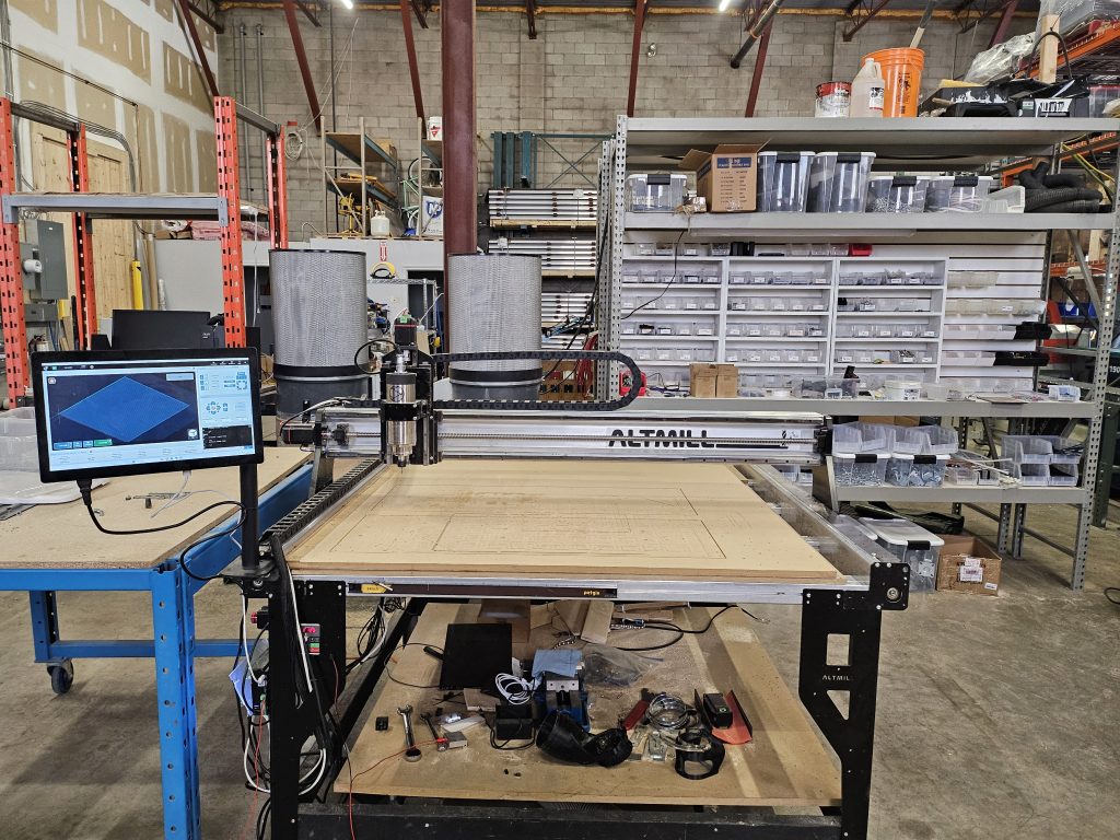
gControl is a panel computer that is designed to be used to control your CNC machine. It runs gSender and connects with your LongMill or AltMill to provide an interface to send commands, jog, change settings, and send jobs. While currently, you need to provide your own computer to run your machine, gControl takes that place.
At this current time, customers are required to provide their own computers to control their CNC machines. Since we don’t have control over the sort of computer, the condition of their device, specifications, and the quality of customer-provided computers, this can be a source of issues. Tackling issues that come from the computer can also be tricky, as we can attribute issues to so many things, such as the machine itself, the electronics, and the connection.
GControl also comes with Windows 11 IOT installed, a special version of Windows designed for applications that require a high degree of reliability. This version of Windows is designed for fixed functions, special-purpose devices, with an expected lifecycle of 10 years or more like medical devices, bank machines, and manufacturing systems. Unlike Windows 11 Home or Pro, Widows 11 IOT comes without bloatware and only performs updates that does not change settings or core functionality and stability of the operating system. We expect that this system will reduce issues that stem from Windows 11 related settings and updates.
By being able to provide a high-quality, tested, and reliable computer, we intend to reduce issues that come from the computer. gControl is essentially an industrial panel computer adapted for use with our machines.
Longevity
Computers used in a workshop setting are exposed to heat, cold, humidity, and most importantly, dust. From feedback from users and the community, dust is one, if not the biggest reason for computers to fail. Dust can fall on sensitive components and cause shorts, or clogged fans to reduce airflow inside the computer, causing them to overheat and eventually die.
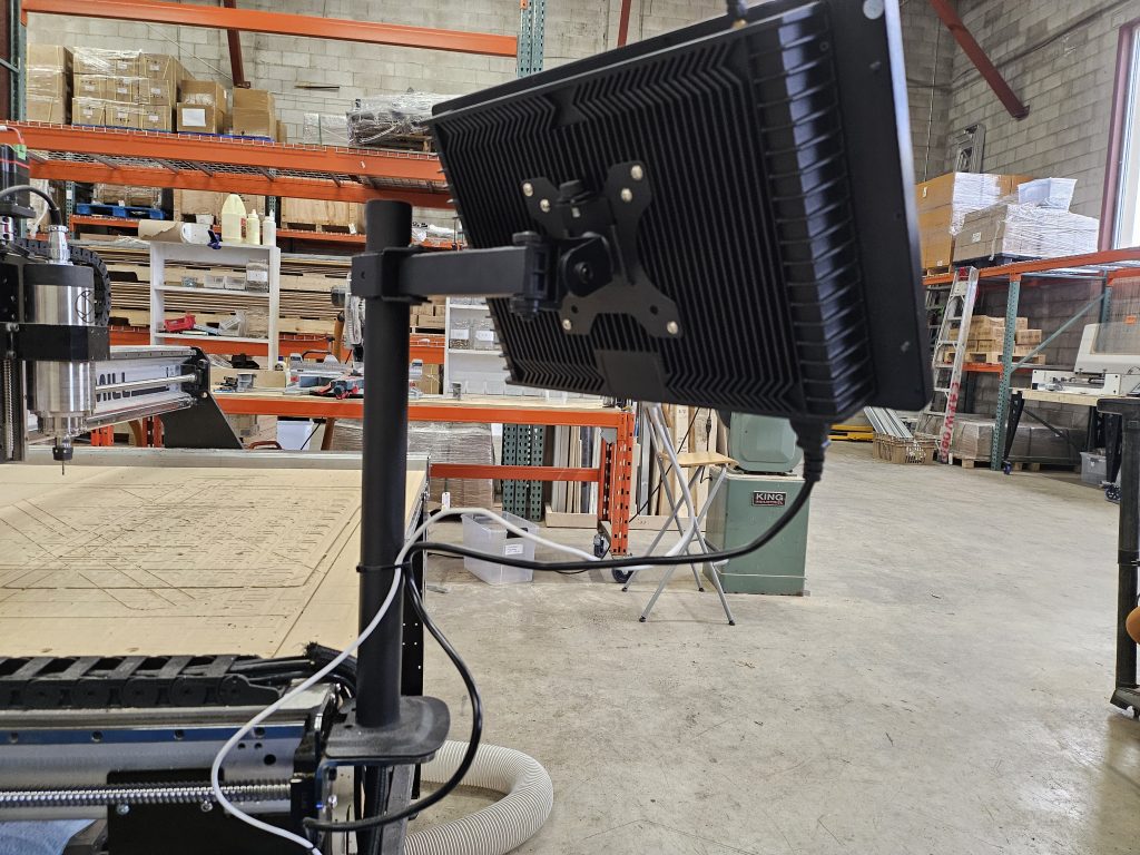
gControl is a fanless design, which greatly improves the durability of the computer.
Fanless design uses a large finned case to dissipate heat
Versatility
There are now a few integrated CNC control solutions in the hobby CNC space. However, one of the main drawbacks is that they are limited to being able to do one job only.
gControl on the other hand is a full-fledged Windows PC, which means that any Windows program you want to run will work natively on the computer. This means you can run CAM programs, and simulation software, check your email, and more, just like you’d be able to with any computer. This also means you can use it for applications outside of CNCing as well.
This means that anytime there is an update to gSender, those updates will apply to the computer as well, rather than having to have it’s own compiling, testing and validation cycle, that comes with embedded systems or custom, locked-down systems.
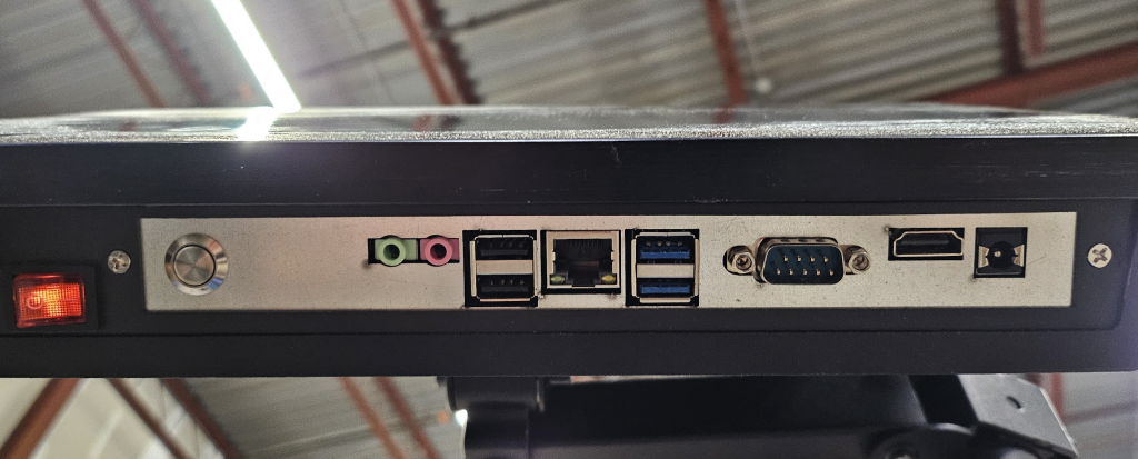
gControl also has many connection options, including Ethernet and USB, which means that you can connect your SuperLongBoard with either Ethernet or USB, plug in external USB sticks and hard drives, and more. Additionally, you can connect other peripheral devices, such as a mouse and keyboard, webcam, and even an extra monitor, if those extras help with your workflow.
Connectivity options
Additionally, gControl comes with standard VESA mounting points, allowing users to also use other mounting options if they so wish.
How I use gControl
I feel that the way I use gControl is probably going to be the same way the majority of users will use gControl.
gControl, first and foremost is dedicated to running the CNC machine which is why all computers come pre-installed with gSender.
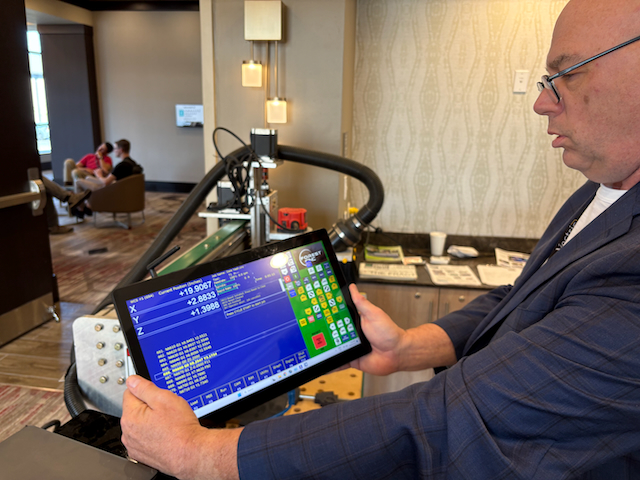
gControl is installed directly on the CNC machine. I am able to tilt the screen toward and away from me so that I have close access to it when I need to jog the machine. While the machine is running, I can clearly see the job status and visualization from a distance.
Windows 11 allows the computer to exist on the network, which means that if I have it on the same wifi network as another computer in my home or workshop, I can directly send files to it. I have one computer I use for making gcode, and I can save files directly onto gControl from my workstation.
Some other convenient options in transferring files is to message it to yourself through something like Discord, email it to yourself, or use cloud storage like Google Drive. At our shop, we have an open Discord channel where the engineers can put the file on the channel from their own computer, then download it on the panel computer.
Otherwise, running gSender on the computer is exactly the same as any other computer.
Pricing
Pricing may change at the time of launch, but anticipated pricing for gContol is:
$430USD/$589CAD for the gControl Panel Computer, bracket, and mountfor the AltMill or LongMill.
Build quality
gControl is a completely fanless computer which dissipates heat through a heavy metal casing. This means that gControl is impervious to the one thing that kills most computers: dust. From our own testing feedback from users in the industrial sector, we can greatly improve the longevity of a computer used in a workshop setting.
Mounting
Each gControl comes with a mount and bracket to attach to the front left or right of the LongMill or AltMill. The mount can clamp to the edge of a table or be screwed in.
This means you can keep the computer close to the action, making it easier to control and watch the machine.
Each panel computer has standard VESA mounting points, so you can also use an aftermarket mount or make your own if you want to set up your device differently.
Window 11 IOT
Windows 11 IOT is a special version of Windows 11 that has some notable differences between Windows 11 Home or Pro that most users will be familiar with, including:
Less pre-installed Windows software, which improves performance and stability by reducing the number of background processes.
Security updates only. Windows 11 IOT does not receive updates with feature or setting changes. This means that Windows stays the same as when it first gets installed. You can still manually install new software and features if you so choose.
Full reimaging and recovery media options. While Windows 11 Home and Pro have limitations on creating computer snapshots/images for recovery use, Windows 11 IOT allows recovery images to be created freely with all customizations and applications saved. This means that if you ever need to revert back to a certain state, you can save that version and reinstall it without restrictions.
10 years of extended support, which means that Windows 11 IOT guarantees support and updates for 10 years. Windows 11 Pro on the other hand receives 2 years.
No regional limitations. While Windows 11 Home and Pro have regional pricing and limitations on where it can be used, Windows 11 IOT allows for worldwide use. This means that we don’t need to carry different licenses based on the country you are from.
Windows 11 IOT otherwise works the same, and any Windows 11 users will be immediately familiar with the operating system, and you will be able to install any Windows 11 compatible software without restriction.
In essence, Windows 11 IOT fits this application since we want to have the most compatible, reliable computer possible for as long as possible.
FAQ
Mostly an anticipated FAQ, since this is just getting off the ground. If you have any questions you can’t find here, please feel free to reach out.
What machines are they compatible with?
gControl, simply put, is just a computer. Any machine that needs to be connected to a computer can be used with gControl. Any LongMill and AltMill with any board and of any generation is compatible with gControl.As a rule of thumb, if it’s compatible with gSender, it’ll work with gControl.
Additionally, other machines like Shapeokos, XCarves, Genmitsus, Sainsmarts, Openbuilds, and others that need a computer connection to operate can use the gControl as well, as long as you download the software for each of their respective companies.
What’s the difference between buying my own laptop or computer?
Both will serve the same purpose. However, the gControl computer comes with all of the hardware to mount it to your machine in a convenient way. Additionally, since it has a touch screen, using a mouse and keyboard is optional. Since our mounting option allows you to put the computer right next to the cutting area of the machine, it also makes it easy to control and operate the machine on the fly for operations like jogging, homing, and probing.
Given that gControl is completely fanless, we also expect it to last much longer in a shop environment than most consumer computer hardware.
What features does it have?
You’ll have access to every feature gSender and Windows computer comes with, including:
Wireless control with a phone
Wired and wireless control using a game controller
Networked file transfer
Access to thousands of Windows programs* such as Google Drive, Chrome Browser, CNC simulators, CAD and CAM software, and more.
*Not all programs are free. Please check system requirements for each program for compatibility.
Is it fast?
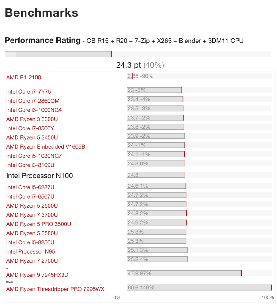
While the Intel N100 chip isn’t considered a high-end powerhouse by any means, it is perfectly suitable for running gSender and many other Windows programs. Check out these benchmarks for more info. In our day-to-day use, we experienced no issues with performance.
gControl also exceeds system requirements for popular software from Vectric, Lightburn, and Carveco.
Processors with similar combined benchmarks.
Can I run design software like CAD or CAM?
Although the main purpose of gControl is as a dedicated control station for your CNC machine, it is possible to run other programs on the computer. We recommend checking system requirements before running your software on the computer.
Can I upgrade my computer?
We don’t recommend opening it up for safety reasons. Users can use removable storage devices like an external hard drive or USB stick to provide more memory.
Whystart with 50?
We feel like it’s a small enough number for us to be able make mistakes and iron out issues on an individual basis, but large enough so that we have a large enough audience to try the first batch.
In our second batch, we’re aiming to have around 300-500 units built.
Can I install Linux or another operating system?
Yes, you can install any compatible operating system on your gControl. gControl should work with many distros of Linux and older versions of Windows.
Please note that :
There may be additional security risks involved with different systems
You may erase or lose files and other content pre-installed
Do I need the internet to use gControl?
No, the computer can be used standalone without any connection to the internet. However, software that runs on the computer may need the internet to work. gControl allows for internet connection with Wifi or Ethernet.
Future plans
Here are our future plans for this computer:
Increase order quantities to reduce overall costs. Since we’re only ordering 50 computers, the price per unit is fairly high. Getting our numbers to around 500-1000 units per batch would reduce the prices significantly.
Explore other uses. This computer is great for running the LongMill and the AltMill. We believe it’d be great to run other CNCs as well.
Thank you John from Forest CNC for letting us test Centroid on your machine.
Testing Centroid on John’s machines from
If you want to share your thoughts on this project, please feel free to answer our survey below.
Hey everyone, we now offer Vectric Aspire on our store!
We’ve taken the jump to offering Aspire in conjunction with the demand for more advanced users.
Why are we offering Aspire?
In the past, our main niche was to serve the beginner, entry-level market for CNCers. However, as our products improved and we continued to come out with new features and accessories, we found more and more advanced users being drawn to our company. We’ve also started playing around with 3D designs and doing some projects where we need the advanced capabilities of Aspire as well.
Now with machines like the AltMill, as well as continued hardware and software advancements on the Vortex Rotary Axis, we’re also better able to take advantage of some of Aspire’s more advanced use cases, such as for making complex 3D models, reliefs, and creating lithopanes.
What is the difference between all of the Vectric software?
We’ll let Vectric explain for themselves. Also make sure to check out their comparisons on their website as well.
Is Aspire right for me?
To be completely honest, although extremely powerful, Aspire is a pretty expensive software. It isn’t something I would personally recommend to a hobbyist right off the bat. If you want to read about my opinion on free versus software, make sure to check out my article. I believe the majority of users, even experienced ones, will be happy with something like VCarve which is less than half the price. Just like with most software, it is possible to get the same functionality by using a combination of software, such as Blender for 3D modelling, and VCarve for the CAM, to get a similar effect. If you’re looking at software options, make sure to check out our Resources as we have lots of different options available.
Aspire however is very streamlined in working with CNC-focused 3D models, plus it comes with many free models that users can modify and change to fit with their projects. We have gotten a number of requests to carry Aspire from a small number of people which I would best describe as the “I want the best and money is no object” group.
Either way, I encourage everyone to do their research and try out all of the different software to find out what works for you. Additionally, even though we have a number of higher-end software options available in our store, we are still very much committed to offering content for alternative software and resources, especially for our beginner users.
Hey guys, I’m sure many of you have been in great anticipation for the close-loop stepper motor option coming for the Vortex Rotary Axis. Here’s a bit of information.
Before we get started, I just want to apologize that we caused some confusion with a number of people, especially new AltMill users, as the current open-loop version that is currently available doesn’t work yet. We should have had some more info ready to share so that people knew what they needed to expect for the Vortex AltMill compatibility. If you haven’t heard from us yet, we’ll be reaching out directly so that you have the support and parts coming so that the Vortex will work with your machine.
Without further ado, below is Daniel’s write-up of what you should know about the Vortex Rotary Axis Close Loop Stepper Update!
First install of close loop stepper and AltMill
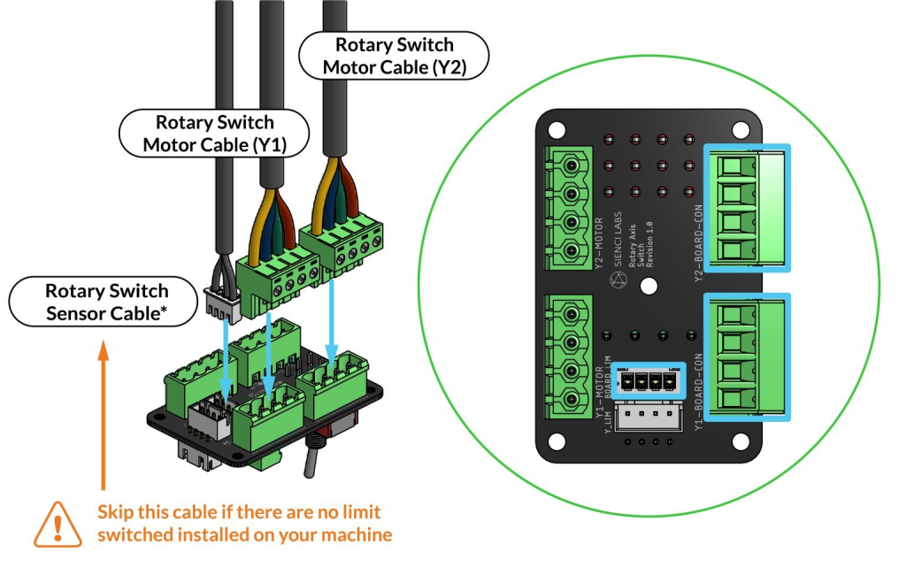
A novel feature of the Vortex Rotary Axis kit not seen with any other rotary axis add-ons is the use of a rotary switching module which ‘intercepts’ power going from the motor drivers to the Y-axis motors and instead sends this to the A-axis, allowing for use of an A-axis which would otherwise be impossible with any regular 3 axis CNC controllers such as the original ‘LongBoard’ controller used on the LongMill.
#image_title
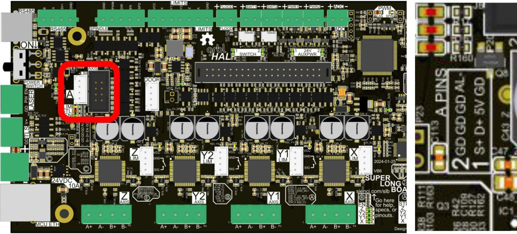
With the release of the new SLB controller used on the LongMill MK2.5, and SLB-Ext controller used on the AltMill, we now have an A-axis specific output. Instead of switching between control of the Y-axis and A-axis, we can now drive both simultaneously and independently.
A-axis control output marked by the red square
Please note that if you have a SLB controller, you can put your own motor driver to control the open-loop stepper motor on the Vortex. Resources and instructions for this can be found here.
Since the AltMill uses integrated drivers with the Y-axis motors, it isn’t possible to ‘intercept’ this control of the Y-axis motors, so we aren’t able to use this same rotary switching module. To use the Vortex Rotary Axis with the AltMill, it is therefore necessary to use the A-axis output, along with a motor and driver just for the A-axis.
Going forward, to complement the new capabilities of the SLB and SLB-Ext controllers shipped currently with the LongMill and AltMill users have the option of choosing the ‘Close Loop Motor’ option to pair with their Vortex Rotary Axis kit. This kit will not come with the rotary switching module, but instead with an A-axis closed loop motor and motor cable that will be installed onto the Vortex.
There are several benefits of this new arrangement:
No more need to toggle between Y-axis control and A-axis control.
The Y-axis motors stay ‘locked’ during use of the A-axis, preventing any possible drift while cutting rotary axis projects.
Higher torque at the rotary axis, with the ability to instantaneously self-correct position, should the position of the A-axis slip under cutting load.
Alarm feedback from the motor to the controller to stop a program if something goes wrong or A-axis position is lost.
Higher possible speed, and higher possible acceleration of the A-axis, to speed up projects with lots of small detail.
Simpler wiring with no need to mount a separate switching unit and two extra sets of cables.
Capability of full simultaneous 4-axis CNC programs, allowing for completely new types of geometries to be machined in one setup.
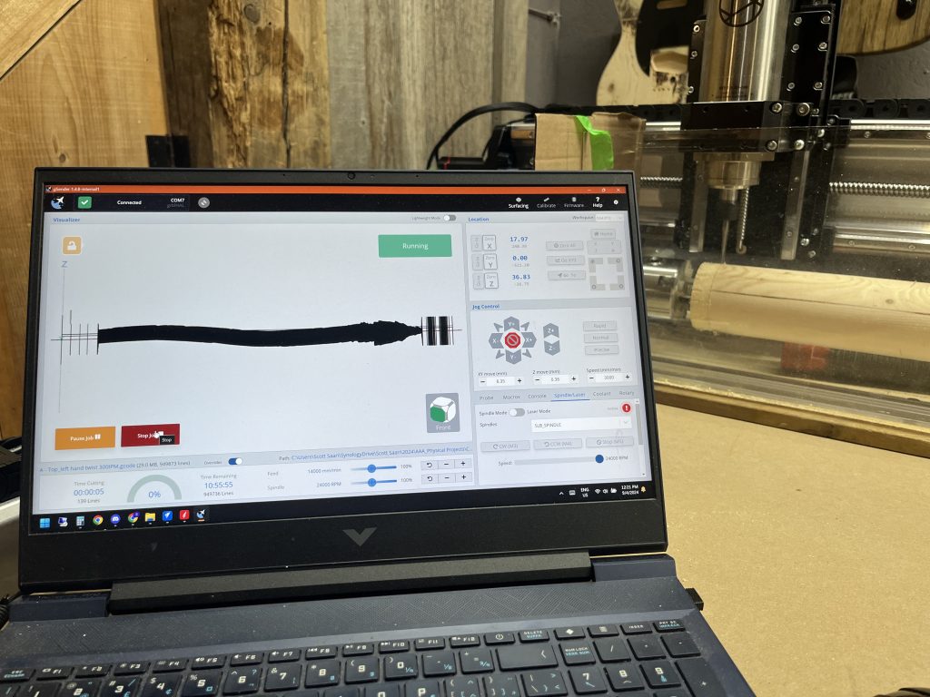
gSender in full 4 axis mode
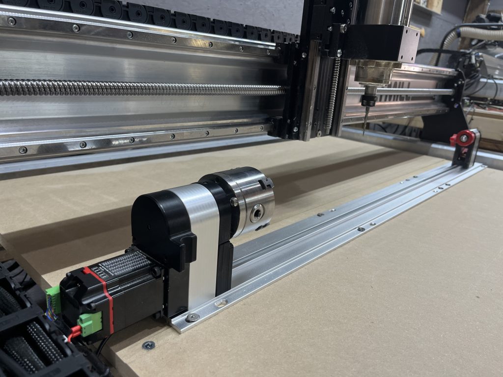
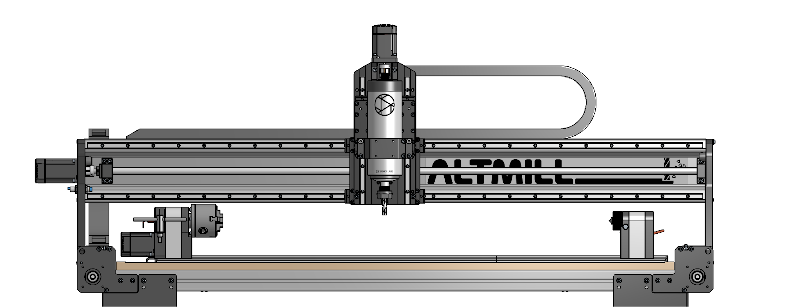
Vortex with closed loop motor mounted on AltMill
Closed Loop Motor Compatibility
If you’re unsure of the compatibility of your CNC machine and the Vortex Rotary Axis kit, please note which controller you have installed with your CNC machine and refer to the following:
30″ and 48″ Open-loop versions of the Vortex Rotary Axis are compatible with the LongBoard controller and SuperLongBoard controller used on the LongMill MK1, MK2, and MK2.5
30″ and 48″ Close-loop versions of the Vortex Rotary Axis are compatible with the SLB-Ext controller on the AltMill and SuperLongBoard controller used on the LongMill MK1, MK2, and MK2.5
The closed-loop motor variation of each kit will have a longer delivery time, and it is estimated to ship out sometime between Oct and Nov.
In the haste of production and development of the first batch of AltMill CNC machines, purchases of the original Vortex rotary axis kit and AltMill in combination were possible and shipped out together, meaning some folks received these two kits without complete out-of-the-box compatibility, as a motor driver for the A-axis would be required as described here.
For these few people affected, we’ll be sending out closed-loop motor upgrade kits to upgrade Vortex Rotary Axis kits for full compatibility with the AltMill free of charge. Customers who had placed an order for their AltMill and Vortex before August 15th included in this will receive a confirmation notice by email. If you have placed an order (or two separate orders) including an AltMill and Vortex before this date and do not receive a confirmation of this by September 18th, please reach out to us with your order number to get this sorted out. These will be shipped out in the coming 2-4 weeks.
Kits will also come with an updated 48” extension track section for improved compatibility with the AltMill.
Hey guys, Johann here. Ever since we announced the Sienci spindle for the Altmill, there has been a tremendous amount of interest from the community in bringing a Sienci-supported spindle option to the LongMill platform. While it has always been our intention to do so, we were busy finishing up the AltMill and other projects, which prevented us from giving this project the due diligence that it deserves.
If you want to read about our previous thoughts, testing, and opinions about spindles for the LongMill, check out this blog post.
The LongMill Spindle and Dust Shoe Kit is now available in our store. First orders are expected to ship August/September 2024
Below is our analysis and additional info about ordering the kit.
TLDR Version
It’s about half as loud as a router
Easy to connect
Offers precise control over your spindle
New features and functionality when paired with the SuperLongBoard.
Offers gains in performance over 20,000 rpm
Orders are open now and will ship August/September 2024
Key benefits
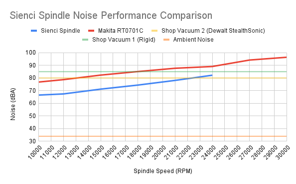
Noise
In a previous survey of the LongMill community, most people placed “lower noise” as their second highest priority feature (only behind auto tool changing).
In our testing, a 1.5kW spindle is consistently 10dBA quieter than the Makita router at every speed, which makes it a drop-in upgrade that is easily half as loud (half the noise every 10dBA). While a water-cooled spindle would be even quieter, we believed that a small amount of extra noise was a reasonable tradeoff to the extra complexity of a water cooling system.
For some context, this air-cooled spindle produces less noise than the quietest of dust collectors/shop vacs in most use cases up to 23,000RPM.
Hear the difference in volume and the quality of sound for yourself
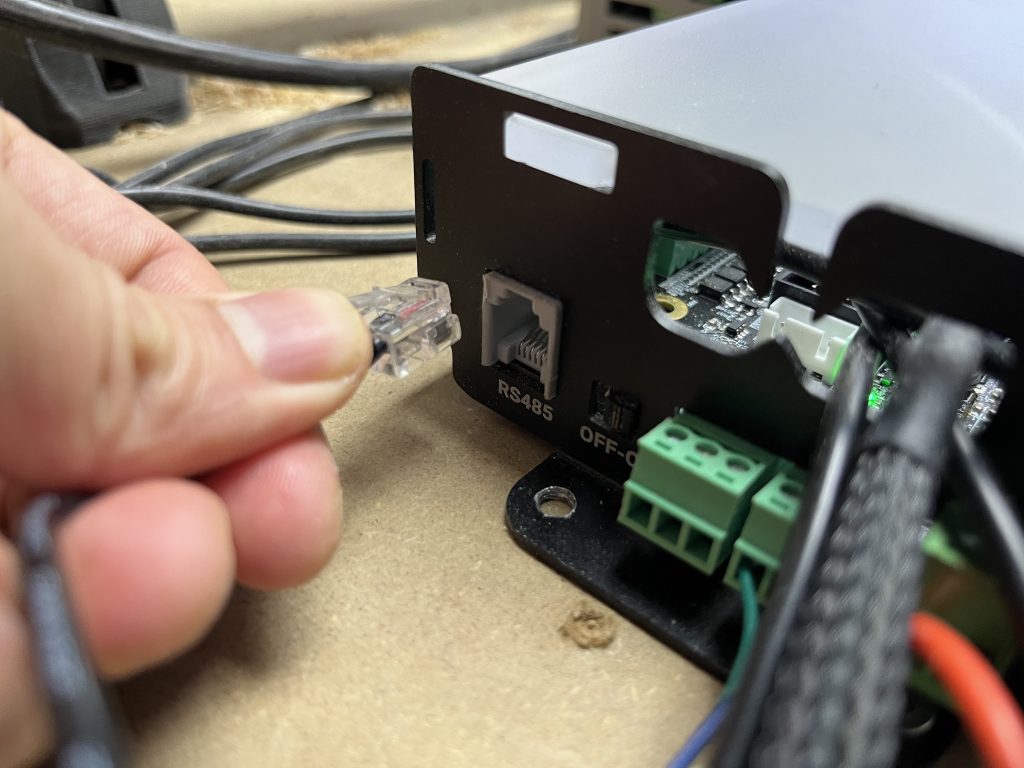
Plug and Play/Easy to Install
The Sienci spindle comes pre-wired, pre-programmed, and connects to your controller with a single RJ11 Cable (a telephone cable). As with all of our other accessories for the LongMill, come with excellent resources and support. We are currently finalizing the installation guide to upload to our resources site soon.
One wire to rule them all
Advanced Spindle Control
Another benefit of a spindle system is that you can control the start/stop and speed of the spindle directly from your g-code sender or gSender. With this digital interface, you:
Can precisely control the speed of your spindle down to the single RPM
Know when your spindle is at speed
Know if your spindle stalls
Communicate between the VFD and gSender to improve the chances for job recovery in the event of a failure
No guesswork speed control
Spindle error feedback
Caveats, Provisos, Warnings, and Disclaimers
Marginal Cutting Performance Gains
This is an area we spent a lot of time and effort digging into since there are varying performance claims floating around the Internet and we’d like to give you our conclusions with some hard numbers. This of course pertains to our product in general, but likely to any spindle kit on the market. We believe we have conducted the most thorough testing and investigation in the hobby space for spindles.
A single run of our cutting test, out of more than a hundred
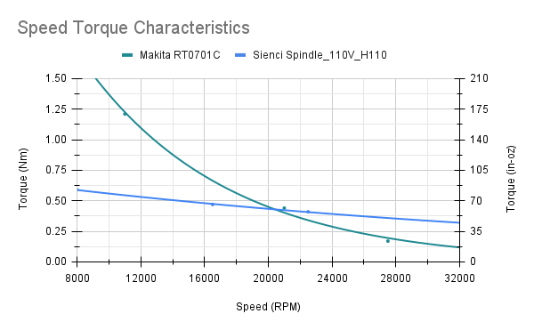
Speed – Torque characteristics of the Makita vs Sienci spindle
Speed – Power characteristics of the Makita vs Sienci spindle
The key takeaway from our testing is that the spindle is not dramatically more powerful than the router. The spindle has more power and torque at higher speeds, while the opposite is true for speeds below 20000 RPM (despite a higher risk of overheating for the Makita).
For 0.25” (¼ inch) tooling, there is little practical difference in cutting performance when upgrading to a spindle since you are limited to 400-500W cutting with the rigidity of the bit. With surfacing, you can use the full power of the spindle, but it also means that you will need to run both the machine and the spindle fast.
Surfacing Hard Maple End Grain at 1.2mm depth and 5000 mm/min (800W-1000W)
SuperLongBoard as a requirement
To take full advantage of the spindle, including the advanced control features detailed above and the all-important partial holding current feature available only with grblHAL, we highly recommend that you upgrade to the SuperLongBoard.
While it is possible to adapt this spindle kit for use on the LongBoard (and we will release more information on how that can be accomplished), here are 6 key disadvantages that you should be aware of:
We will consider this a DIY configuration and support and resources will be limited
Start-stop control will be unavailable without a reflash of the firmware and additional components
The VFD will have to be re-programmed
Holding current must be applied in full which can overheat the drivers and motors
No stall detection or any other advanced features that are currently in development
High-speed machine movements (>4000mm/min) that suit the spindle are unavailable due to legacy driver stability issues.
Dust shoe hose size
The spindle is designed with dust collectors, not shop vacs in mind and as such fits 4” dust hoses by default. To use shop vacs with the dust shoe, you will need to purchase a commonly available 2.5” to 4” adapter (Example found here on Amazon). We are trying to see if we can offer an adapter at some point, but there are no commitments on this item just yet.
Additionally, the original dust shoe used on the LongMill is not compatible with the 80mm spindle. The kit comes with a larger dust shoe included.
The dust shoe performs well with a shop vac attachment
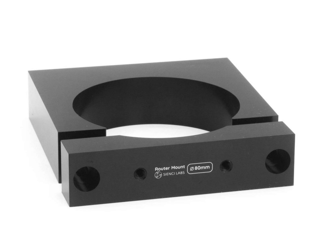
Spindle Mount
This spindle is 80mm in diameter and the mount will be included in the LongMill Spindle and Dust Shoe Kit.
The main difference between the AltMill Spindle and Dust Shoe Kit and the LongMill Spindle and Dust Shoe Kit is the addition of the 80mm mount. You can also purchase the mount separately from our store.
Additional Information and Insights
Cutting Volume and Accessories Compatibility
We’ve checked the spindle + dust shoe against every single LongMill configuration ever released (including the MK2 extension kits), and there is no loss to cutting volume to any configuration (the MK2 front feet can technically can collide with the dust shoe, but the overlap is only 2mm (1/16”) and only occurs when you are cutting below the wasteboard).
The story is a bit different with the Vortex which is a lot more height constrained. The additional length of the spindle collet eats into the cutting (and probing) height requirements of the Vortex, and for every machine configuration we recommend raising the feet of the machine up by 1.5” (2 sheets of 0.75” MDF) to restore the original cutting volume.
Insufficient clearance for the Vortex without raising the machine
Weight of Spindle and Mechanical Effects
The new spindle is 2.8kg (6lbs) heavier than the Makita RT0701C router’s 1.8kg (4lbs) which may seem a lot, but according to our calculations and testing, this has a negligible effect on the X and Y axis, requiring only an extra 1-2% of available torque from the steppers motors even accelerating to 5500mm/min. The remaining torque should also be sufficient in making the hypothetical 1.5kW cuts which typically require less than 100N in cutting force.
Force generated by the stepper motors at varying speeds
Force requirements for a 1.5kW cut
Jogging the machine at full speed
With regards to the Z-axis, the additional weight can consume up to 27% of total available torque of the motor. Having said that, since boring operations typically involve pushing the bit down into the material, the additional weight is not an issue in such a scenario.
Making a few holes in walnut
Lastly, it’s also worth mentioning that although the steppers can hold and push the spindle with an adequate amount of force, aggressive cutting can still result in significant deflection of the bit and cause your cuts to come out untrue, so after any aggressive cuts, you should always follow up with a skim/spring or finishing pass to make sure that the surface is accurate and smooth.
Conclusion
While the Makita RT0701 is an excellent option and recommended for most LongMill users, the Spindle Kit offers a high-quality, simple, and well-supported option for the community. To learn more and to order, make sure to check out the store page here.
Docs The lead time for this item is 3 days. The LongMill Spindle and Dust Shoe Kit is designed to unleash the capabilities of the LongMill as a plug-and-play replacement for the standard Makita RT0701 router. Each kit comes with: 80mm Dust Shoe 1.5KW 110V Air-Cooled Spindle 110V, 1.5KW, 3-Phase VFD…
For those of you that have followed us as we develop and improve our products, or read Andy’s Production Updates, you probably know the drill by now – it’s time for our LongMill CNC to see some new improvements!
History
The LongMill used to be called just that when we launched it back in October of 2019, but the naming quickly got expanded:
LongMill V2 which began shipping March 2020
LongMill V3 (Aug 2020), then V4 (Jan 2021), then V4b (Aug 2021)
LongMill MK2, which marked a complete redesign of the LongMill CNC to continue our focus on ease of assembly, rigidity for price, and designed with add-ons in mind. This began shipping in March 2022 and retroactively grouped all prior LongMills into the “MK1” naming.
LongMill MK2.5 which we will now be ramping up to begin shipping for June 2024
Why do we make these updates? Since we launched the LongMill, we’ve continued to maintain a solid idea of where we felt it should sit as a CNC and more generally as a tool. If you’re looking for a CNC that can create any reasonably-sized project an individual would be looking to make at home with great support and reliability, it’s the machine for you. It’s akin to a home printer, you could save money and spend less on stamps or small label-makers, and you could also spend a lot more on a large laminate printer or printing press, but the home printer can really hit the sweet spot for most individuals. We’ve never wanted it to trend upwards in price and features until it starts to resemble an industrial piece of machinery (that’s what our new AltMill is meant to do), but we also recognize that we can take action when opportunities arise from:
User feedback
Production at scale as our company grows
New understandings of our users priorities as we see how everyone uses our CNCs
Making steps while ensuring that the changes are worth our time and everyone’s money makes us feel that we’re continuing to update our products with the best that we have to offer to the CNC community. This is exemplified by the transition from quite a few 3D printed parts in the original LongMill to now being all metal and one injection mold in the MK2.5. Another example is the MK2 redesign which made the LongMill 2-3 times stronger than the MK1 design for the exact same cost and nearly halved the assembly time. All of this with very few price adjustments along the way to keep up with changes during COVID, inflation, and continuous improvements we continue to pour time and energy into to build and support such a user-friendly machine and ecosystem. Would you believe our 30×30 model started at $950 and by the MK2 it was still only $1350 USD?
What’s changing?
We’ve got two new heavy-hitters that we’re very excited to announce as a part of the MK2.5 update, alongside some other smaller improvements.
SuperLongBoard
Many of you might already be familiar with this new development that’s been over 1.5 years in the making, but if not we have many priorblog posts that can bring you up to speed. The bottom line is that with the successful launch of the first 500 pre-ordered units and the positive reception, we’ve decided to fast-track the SLB to be standard with the LongMill moving forward (it’s also what we’ll be building off of to power our new AltMill CNC).
Since my last SLB update, we released a great summary video on what you can look forward to that also explains why we think it makes sense to move forward on this new electronics architecture. The main benefits to all users will be:
Faster movement, homing, and probing from new motor drivers that are more robust and anti-resonant
Smarter drivers also reduce motor noise, allow changes on-the-go over firmware, and are expected to be more reliable
Improved cutting reliability against ruined jobs and material due to high-grade EMI measures implemented in the board redesign which also includes Ethernet connectivity
Smarter and more responsive system resulting in faster probing, safer E-stop, and room for even more future expansion
Even more extras for the true enthusiasts like RS485 VFD support, 4th axis cutting, TLS, and more
It’s been very exciting seeing the SLB get into peoples hands over the last two months, especially so after some have already contributed their own guides and videos showing installation, reduced motor noise, and increased speeds. I was getting concerned that the shipping status table posted in the last SLB update would encounter more delays but I’m happy to say that we were able to keep things relatively on track in that first batch. I really appreciate everyone’s understanding and patience as we’ve been preparing to get more SLBs in for MK2.5 and also the lineup of already another hundred or so orders from people looking to upgrade their existing CNC systems. The strong reception we received in the initial pre-orders, combined with the feedback we’ve gotten so far from them in action, is what makes us confident in rolling out the SLB to everyone else for MK2.5. We’ve already had many more updates to our docs from the wider feedback such as:
Troubleshooting when the SLB is too fast for your machine
Post processor selection
Options for new options for motor holding
Clarified RGB LED strip hookup
Clarified 4th axis driver hookup diagram plus extra firmware setup steps
To all those who back-ordered their SLBs, don’t worry you still have your place in line since MK2.5 was always meant to be a part of this same batch of boards. Currently we’re still doing our best to have the boards ready to ship out by end-of-May but it seems that there’s been another delay from one of our manufacturers which might mean that we won’t have boards show up until the start of June.
Spring Loaded Anti-Backlash Nuts
There’s also been a lot of coverage documenting our long process in trying to figure things out with these, but now we’ve gained confidence we can produce them in bulk and are excited to introduce them as a part of MK2.5!
Since we premiered this new part, demand has remained super high and every time we’ve restocked it’s sold out in just a couple days. The reason people have jumped to buy the over 4000 we’ve made so far is that it offers self-adjustment to maintain no backlash on all the LongMills axes. This is normally a very expensive technology to access, and is normally solved on other CNCs by using ball screws (more expensive and require more cleaning maintenance) or belts. To-date we’ve used an OpenBuilds-based design that allows for no backlash on lead screws but requires manual adjustment, but with this new upgrade it means one less step for y’all to have to worry about when it comes to CNC assembly and maintenance; giving you a reliably precise CNC system while still having the benefits of the low maintenance of lead screws.
Other Updates
Some other updates that were already introduced during MK2 shipping were new coupler and clamping nut designs that now use M5 hardware instead of M3. This change has meant that we have mostly eliminated people having issues with stripping hardware (some of our users have gorilla grip) or not being able to tighten them down hard enough on the lead screws.
We’ll also be rolling out injection molded feet which will be replacing our currently 3D printed middle feet. These support the Y-axis rails to create a more rigid system, but these parts have never really caused any issues or showed signs of needing an upgrade, we just haven’t changed the design for a while now so we decided to save the time for our 3D printer farm and opt for higher-quantity manufacturing.
Summary
We’re excited to announce everything that’s on the MK2.5 docket! Due to the changes, MK2.5 will also be coming with an approximately $150CAD/$110USD price increase compared with MK2 to reflect the addition of primarily the SuperLongBoard and the other additions.
We are continuing to work our way through the materials from Batch 8 (MK2) and are waiting on Batch 9 (MK2.5) parts to arrive which we expect to start shipping out later in June. We’re also already underway on putting together new revisions of our assembly manual and other LongMill resources and are looking forward to continue further expanding those resources in the coming year in other areas as well.
Of course, as MK2.5 starts to arrive in users hands we’ll continue to bring any other improvements we can like we’ve done for all prior LongMills, and anyone who’s looking to manually upgrade we already list all the new parts on our store for individual purchase. Also if you ordered a MK2 that hasn’t shipped yet and you’d be interested in upgrading to a MK2.5 instead, please just call or email us to arrange paying the difference and we can happily update your order.
Hey guys, it’s Andy here. We’re excited to be launching a new CNC machine, the AltMill! This article is designed to tell you everything about the AltMill that we possibly can.
The AltMill name is derived from “alternative”, “alter”, and “mill”. We believe that “alternative” fits the namesake of the AltMill because this machine represents a different way of approaching things in engineering, technology, and the way we build our company as a whole. We believe “alter” fits the purpose of the machine, which is to take materials and alter them into new forms, uses, and purposes. And of course, since we use milling as our way of altering the material, we can put these ideas and words together to form the name “AltMill”.
The AltMill is a culmination of new technologies, hardware, experience in manufacturing, and customer feedback. Our goal was to take all of these things and build a machine we felt brought the most value to the CNC user by incorporating our ability to engineer high-performance, quality machines at scale.
Differences and Similarities Between the AltMill and the LongMill
The focus for the LongMill was to be a medium-format, hobby-focused CNC machine. Most users typically are looking to make things with a CNC in their spare time. Because of this, we made the LongMill the most affordable option possible in this size category, while being useful and effective enough to handle just about any CNC woodworking project you want to throw at it. We define LongMill’s success in its ability to make CNCing accessible to the average person.
The AltMill is designed to have the most “effective value” as possible. Its success is defined by how much value it can create versus the cost of the machine itself. In simple terms, we wanted the machine that would bring the highest ROI and productivity. The AltMill focuses on the intersection where we believe the performance versus cost ratio is the highest it can be for these users.
Here are some spec comparisons to highlight the differences between AltMill and LongMill:
We’ve tested the AltMill to over 830IPM (although regular cutting speeds are in the 250 to 500IPM range) in cutting speed, while most projects we run on the LongMill run at 100IPM.
Based on our deflection testing, the AltMill is approximately 8x more rigid than the LongMill.
While the LongMill’s main bottleneck in cutting speed is in motor power and rigidity, the AltMill’s bottlenecks are in spindle power and the strength of the endmills. We estimate that the AltMill could handle upwards of 6KW of spindle power (although it’s not likely we’ll dive into that anytime soon because there are a lot more expensive electrical requirements we need to tackle to get this set up for the average user).
That being said, there is an overlap between these two machines. The process of using the AltMill is basically the same as the LongMill, which means that our resources and education translate over between the two machines, and the ease of use and process of using of both is similar. Additionally, both machines are designed primarily for woodworking use, and the types of projects we expect users to create will be similar as well.
Should I get the AltMill or the LongMill?
This depends primarily on your budget and what you want to do with the machine.
Here’s why you would want a LongMill:
You are budget-conscious. The total setup cost for the LongMill is roughly half the cost of an AltMill. Additionally, replacement parts and maintenance is cheaper overall.
You have limited power in your shop. We recommend having two breakers to power your LongMill and accessories such as the computer and dust collection, but in some cases, you can get away with one. On the other hand, you may need to connect the machine, dust collection, and spindle on separate breakers depending on power availability in your shop.
On the other hand, here’s why you would want an AltMill:
You need speed. The AltMill can cut significantly faster than the LongMill. We regularly run the AltMill over 5x the recommended milling speeds compared to the LongMill. The productivity of the AltMill is much higher.
You need more working area. The largest version of the LongMill has a working area of 48×30″, whereas the AltMill can cut 48×48″. This means you can process half of a standard 4×8′ sheet in one setup.
You need more precision. With ball screws and linear guides, the overall precision of the AltMill is better. In practice this may not matter as much with woodworking projects, you may see a bigger difference in the accuracy of parts for materials like aluminum.
AltMill Budgeting
Of course, the higher performance of the AltMill comes at a cost. We discussed the breakdown of costs one should expect with the LongMill in our article here. Here are some rough estimates on what you should budget (in USD).
Based on my estimates, you should budget around $4500USD to fully set up an AltMill from scratch, about double the cost of the LongMill. You may have some of these items already which will lower your costs.
#image_title
The machine itself ($2950USD)
This is the machine and all the doo-dads to have a working machine, minus the spindle, wasteboard, and computer.
Unlike the LongMill, the AltMill comes default with table legs, so you don’t need to build a bench for it. Additionally, the AltMill comes with inductive homing sensors by default.
Based on our rough estimates, shipping within US and Canada should cost between $150 to $200USD.
Spindle and dust shoe ($515USD)
We recommend users to use a spindle with their machine, because running the Makita router on the AltMill will make the life of the router very very short and unenjoyable. We expect the majority of users to order the Spindle and Dust Shoe Kit which we offer as an add-on kit.
For users wanting to add their own spindle, we expect after all of the parts, wiring, and extra things you’ll need with the machine, it’ll run around $500USD on the low end, but could cost up to a few thousand dollars for some really high end spindles.
We are offering a 1.5KW 110V spindle at this time because we believe it will accompany the most number of people at the launch of the AltMill. However, we will likely offer higher-powered spindles requiring 220V in the future. Users planning to implement higher power spindles should also budget the cost of hiring an electrician for any extra work.
Dust collection ($300 to $1000USD)
Assuming you get the Spindle and Dust Shoe Kit from us, the dust shoe comes with a 4″ hose mount. To get the full performance from the AltMill dust shoe and to keep up with the cutting rate of the machine, a dedicated dust collector should be used. A regular shop-vac can be used, but may not be able to keep up with the waste material generated by the AltMill when running quickly.
At minimum, you will need a computer to run gSender to control the machine.
Wasteboard ($50USD)
Like the LongMill, you will need to mount a wasteboard to the machine. A 4x4ft sheet of 3/4″ is recommended as the base. On the AltMill, the wasteboard is mounted to it’s frame using screws. You can additionally purchase t-tracks if you wish to add some workholding to the wasteboard directly.
Tooling ($100-200USD)
You’ll also probably want to order some endmills and bits for your machine. You can use the same tools between the LongMill and AltMill, although we will likely expand our range of endmills to accommodate the larger collet sizes we can use with the AltMill spindle. Tooling costs vary widely, but we sell affordable end mills on our store.
Software ($0USD to $699USD)
The AltMill works with our free gSender for all of your machine control needs, along with additional features such as machine calibration, firmware changes and updates, surfacing g-code generation, and more.
For CAM, all of the software that works with the LongMill also works with the AltMill. You can learn more from our Software Resources. There are both many free and paid software options for the AltMill.
The most popular software, and the one we recommend frequently is VCarve Pro, which offers advanced 2D and some 3D carving features, flip-milling set-ups, 4th axis support, and more. This software has a one-time cost of $699USD.
What to Expect When You Get an AltMill
Please note that at the time of writing, we are starting the first production run of the AltMill. You may find relevant information about the Order Status page or in our Production Updates in the blog.
Shipping and Delivery
The AltMill comes in three large boxes. They have been specially designed to fit compactly to reduce shipping costs as much as possible. We estimate each box will weigh about 70lbs. With UPS or other courier shipping, you should expect transit times within the US and Canada to take around 1 week.
Packaging mockup
Based on some general shipping cost calculations, customers should expect to pay around $150-250USD for shipping within the US and Canada for an AltMill.
Set up and Assembly
Large portions of the machine will come pre-assembled, but final assembly of joining the sub-assemblies will be necessary. Most of the machine is put together with M5 and M6 screws, and a set of metric bits or allen keys are required to finish the assembly. Additionally, you will need to provide and mount your own wasteboard. We recommend using 3/4″ MDF.
We will have resources to help users set up and assemble their AltMill on our Resources in a similar style to the LongMill and other products we’ve created. Users should allocate between 3-5 hours for the assembly and set up.
Users will also need to provide a computer that can run gSender. More information about downloading gSender and details about its setup can be found in the gSender Resources.
Operation
The AltMill works just like the LongMill and most other CNC machines. We’ll provide more guides on setting up the machine for different types of work. Beginner users may find content in the LongMill Resources relevant. We expect this group of users to be a bit more advanced, and some of the content and information will reflect this. Additionally, users should expect revised content such as updated feed and speeds and installation for the add-ons to come soon.
Maintenance
The AltMill maintenance is simple, but needs to be done regularly to prevent damage to some of its components and have optimal performance and longevity.
Here are some estimates for bearing maintenance:
Ball screw and supporting bearing components should be greased every 3000-5000 hours, or a small amount of greasing done more frequently
Linear guides should be wiped and oiled for every 100km of use. With full-time use, users should oil their linear guides every 3 to 4 weeks.
We will provide thorough resources and guides to perform proper maintenance for the AltMill.
Engineering
Extrusion Design
The process of designing the LongMill extrusions gave us a lot of experience in designing extrusions for high precision and rigidity critical applications. Since then, we’ve used this knowledge to manufacture parts such as the t-tracks and the enclosures for the SLB. This experience was able to help us understand the quirks and strengths of aluminum extrusion in the construction of the AltMill.
The AltMill extrusions are big, especially compared to the LongMill, which lends to its strength and rigidity. If you want to check out the video where we talk about this more, see it below:
Clip from the video
To make sure that the frame and axis of the AltMill are straight, a few additional steps have been incorporated to make extract as much performance and accuracy from the extrusion as possible.
First is in our process of extruding and milling the critical surfaces flat. Once the extrusion is pressed, it gets annealed and straightened, which allows for fairly high tolerances. However, there can still be sub-tenths of a millimetre deviations in the tolerance and straightness of the extrusion. To eliminate this, mounting surfaces for the linear guides and the ends of the extrusions have been machined to ensure they are flat and parallel.
Second, additional extrusions that make up the base of the machine are designed to help keep the Y-axis rails straight and parallel. Each of the bottom rail ends have been machined to make sure they are of an exact length, so the distance between the two Y rails is extremely accurate. This also provides additional support and rigidity to the machine, plus having mounting points to make it easy to add a wasteboard to the machine.
Test assembly of the AltMill “bench”
Users will find that the extrusions also come with many different design aspects, such as t-tracks and mounting points for motor components, legs, drag chains, and more, allowing the machine to be easier to assemble and maintain while saving costs by reducing the number of parts needed to build the machine.
Design for Shipping
One of the challenges that come from getting a CNC machine, especially a large one, is getting it from the factory to the door. Most machines in this range do need to be shipped in multiple boxes and the AltMill is no exception.
To make it as inexpensive as possible to ship, we have made a lot of considerations such as:
How can we maximize the travel of all of the axis while keeping the rails as short as possible?
How can we keep the weight of the machine low while being structurally rigid?
What items are we going to make default or optional, and how will we design the packaging around these considerations?
What sort of weight and size can the packages be and how will it affect handling?
The AltMill is designed to come in 3 large boxes weighing around 60 to 70lbs each.
Design for Assembly
Because of the more complicated procedure for assembly of the AltMill, a lot of consideration was made to make the machine as easy to assemble as possible internally. Here are some considerations for the design for assembly:
Mounting surfaces for high-precision components like the linear guides and bearing blocks are machined and toleranced to help initial assembly onto the rails and gantries pre-aligned.
We’ve worked with our fasteners manufacturer to use custom make screws with pre-applied thread locker, reducing the chance of screws coming out from vibration and avoid the need to apply thread locker manually
Reutilization of linear guide assembly procedure, testing, and torquing of screws to ensure smooth movement of the assembly used in the LongMill Z-axis.
Machining tolerances for the AltMill X-axisBack of the X-axis gantry where the linear guide blocks mount
Linear Guides and Ball Screws
One of the biggest differentiators between the LongMill and the AltMill comes from the use of linear guides and ball screws. While the LongMill’s v-wheels and lead screws offer an affordable, simple, and forgiving linear motion experience, ball screws and linear guides offer another step above in precision and rigidity.
Our ability to integrate linear guides and ball screws comes from a few different areas of expertise we’ve developed over the years and additional research and testing we’ve done in this project.
Linear guides and ball screws are much more expensive than v-wheels and lead screws. However, we have been able to source them at a lower cost because we are able to order them in larger quantities. For context, ordering them at wholesale can cost 1/3 or less than retail prices, and we can pass those savings onto the customer. Second is our ability to understand the differences and context of the cost and in-practice differences between different linear motion components. The AltMill doesn’t use the highest-end, most expensive components because we know that for our users, they won’t experience or notice the benefits of it. By being able to balance cost and performance, we’re able to choose the right components for our application.
We’ve also had the chance to work with different linear motion components in the production of the LongMill Z-axis, as well as through other internal projects. Through this experience, we’ve been able to better understand the process of assembling and working with different linear motion components at scale, see firsthand the results of long term use and lack of maintence through LongMill users, and test linear motion parts from different designs and manufacturers.
We do expect some new challenges with working with linear guides and ball screws, mainly in educating users on proper maintenance of these components. While these components can last a very long time, proper cleaning and lubrication is critical to make sure they perform properly. From our experience, the biggest factor in the longevity of these components is in the proper lubrication. It should be noted that one of the main downsides of using bearing-based linear motion components is that lack of lubrication can dramatically accelerate wear and cause catastrophic damage. To mitigate this, we plan to provide proper instruction and lubrication supplies to make it easy for users to perform proper maintenance for their machines.
Tramming Functionality
For those who aren’t familiar, tramming is the process of adjusting the position of the router or spindle, typically by tiling it forwards and backwards, and/or left to right. This ensures that the cutting tool stays aligned with the Z-axis. Having a machine out-of-tram can result in things such as ridges or artifacts, especially on surfacing operations with wider bits.
The AltMill, as far as we’ve been able to find, is the first hobby CNC machine to have nod adjustment, allowing for the X-axis rail to tilt slightly forwards and backwards, eliminating the need to shim the spindle mount. Additionally, the AltMill offers tramming on the spindle mount, which allows the user to move the mount left and right slightly as well.
A combination of an eccentric bushing and shoulder bolts are used in the Y gantry and X-axis to provide nod adjustment (bolt removed for clarity) Similar to the nod adjustment, the router mount uses an eccentric bushing to adjust left-right alignment
I should note that the eccentric bushings are only used for tramming. In the regular set-up, they have a bolt securing through them, or a shoulder bolt which aligns them to the gantry by default. Also, I should note that currently the tramming for the Z-axis is only built into the default 80mm mount. We do have mounting options for the LongMill 65mm mount, but this does not have tramming.
It should be noted that having the machine assembled in the default position will be within spec enough for virtually all users. Most of the relevant parts are machined to very high tolerances, and there are also many reference mounting points and hardware to help have the machine aligned and straight out of the factory in the assembly process. It is unlikely users will be able to easily make meaningful adjustments without tools like a tramming tool or gauge and a surface plate, and we recommend keeping the machine at its default position.
Why did we add this as a feature? To be completely honest, I hadn’t even thought about it, but one day when I asked Daniel if he’d thought about it, he just shrugged and said he designed the whole thing just for the heck of it.
SuperLongBoard
While the SLB initially started off as a project for the LongMill, many of the technologies and improvements will be present in the AltMill as well. We are currently in the development of a new version of the SLB (code named ALT-SLB or SLT-EXT) that will allow the use of external drivers that the AltMill uses for its motion system.
SLB-EXT, with plugs for external drivers
The main focus of the SLB was to improve stability and reliability of the LongMill’s motion control. We believe the development in this area will translate to rock-solid connection between gSender and the controller. Additionally, on-going development to have a dedicated, on-board computer will be able to be used for both the AltMill and LongMill.
There are some other important aspects and features that we believe are very relevant for the AltMill, including*:
RS485 Spindle control
Communication between the controller and computer using Ethernet and USB-C
Programmable physical buttons to trigger g-code commands and functions such as homing, moving the machine to a corner, and more
Tool Length Sensor and Tool Changer support
Ability to manage more pulses per second for higher motor speeds
Squaring and calibration functionality
Full independent 4th axis support
*Please note that some of these features are in-progress and are not ready for release yet.
Along with the “brains” of the board, we are also working on an external power-switching system to distribute power to the motors and interface with the e-stop to ensure the power is cut completely in the case of an emergency.
It should be noted that the SLB and the SLB-EXT are not interchangeable. The SLB is primarily focused on being a controller designed to be plug-and-play with the existing motors on the LongMill, and does not support external drivers for the X,Y, and Z axis. The SLB-EXT does not have integrated stepper drivers on board and must use external drivers.
48V Power Supply
During the pandemic, due to the chip shortage, the original power supply that we were using for the LongMill became extremely expensive due to a specific chip needed for manufacturing. Because of this, we spend a lot of time looking into alternative power supply designs. By switching to a design more commonly used in lighting applications, not only were we able to decrease the cost of the stepper motors, we were able to improve the reliability of the power supply because we were able to internally encapsulate the components to protect it against moisture and vibration. Additionally, we were able to more easily make larger power supplies because of the improved heat dissipation properties of the new power supply.
With this change, we’ve seen a dramatic decrease in power supply-related issues for the LongMill while being able to provide more than 20% more power than the previous design. The AltMill power supply offers nearly double the power of the LongMill power supply at 48V, which allows for additional benefits.
The main benefit of a 48V system is the ability to run the motors faster. Stepper motors lose torque the faster they turn, which means that the faster the machine moves, the more likely it is to lose steps. Increasing the voltage allows stepper motors to “flatten” the torque curve, allowing more torque at higher speeds. With our initial testing with open-loop steppers, we were able to see some small gains in motor speed by about 20%.
Closed-loop stepper motors
When we first started prototyping and testing the AltMill, we quickly found out that one of our bottlenecks was the speed of the open-loop steppers we were using. Over the last few years, the technologies behind motor control has greatly improved, and the cost of these components has come down as well. Additionally, because of our ability to purchase the components at a higher volume, we’re able to also make the machine as a whole more affordable as well.
Closed-loop steppers are motors with an encoder that provide the driver with feedback on the position of the motor. With this information, the driver can correct the position of the motor in real-time, compensating for lost steps and adjusting power consumption based on speed and load.
With the LongMill open loop steppers at 48V, we were able to hit speeds of around 4000-5000mm/min. With the new closed-loop motors, we were able move the machine at around 25,000mm/min before the ball screws start vibrating and jam up the machine. We were also able to push the AltMill all they way to 5000mm/min^2 acceleration rates, 6-7 times higher than the LongMill’s defaults.
There are a number of additional features that make the closed-loop steppers an exciting part of the AltMill because:
The motors can detect crashes and jams, then send an alarm to the controller to automatically shut down the power and spindle down, making the machine safer
Because of the higher efficiency, they can run cooler and a smaller power supply than what an equivalent open-loop stepper system would need
Noise and vibration are generally lower
Spindles and VFDs
Given how powerful the AltMill is, having a spindle is a must. Looking into different spindle options has continued to allow us to look into many different considerations when it comes to picking the right one.
Testing deflection on a spindle
As I talked about in the past in this article, the quality of different spindles varies widely. Because of this, we’ve been hesitant in offering a spindle option since we knew there would need to be a lot of work involved in finding the right manufacturer for it. However, now that we need to get one for the AltMill, we’ve learned a lot about them. Here are some of the considerations about the spindle sourcing including:
The bearing quality, size, and configuration and how it affects the longevity of the spindle
The deflection from the spindle itself
Cost and availability
Cable quality and durability
EMI
Communication protocol like PWM, analog 0-10V, and RS485
VFD efficiency and control technologies like vector control
Programmability and ease of use of the VFD
Collet quality and size
Runout
We have a pile of VFDs and spindles in the testing phase. We haven’t settled on a specific combination yet, but we are planning on choosing one soon.
At launch, we plan to offer a 1.5KW 110V spindle that can run off a regular North American outlet. We are currently in the process of testing a 4KW spindle option that will require more power.
Table Legs
One of the main reasons why we didn’t end up making a 4×4′ LongMill is because we would need to move away from the “mount the machine to a big piece of MDF” design. Basically, since the machine needs to be larger than it’s working area. If we wanted to go for a 4×4′ working area, the material the LongMill sits on would need to be a bit larger (probably around 6×6′).
I should also add here that the main reason we chose a 4×4′ working area for the AltMill is because most standard sheet goods like plywood and MDF come in 4×8′ sizes, so the AltMill can process half the sheet at a time. I should also note that because of the back end of the machine is open, you can pass materials through the back, so you can put the full sheet on, cut into it, and move it out the other end without cutting it in half.
AltMill table mockup
If we were to have the AltMill come without legs, users would need to have a larger bench, also about 6ft wide and long, to accommodate. If you took two 6ft wide workbenches from your hardware store and put two of them together, you’d probably be paying around $800 for the pair. The extra legs on the otherhand, cost about $150USD and are made from bent and welded sheet metal in a local shop near us.
Additionally, the AltMill carries a lot more inertia when it moves, which means that the structure it sits on needs to be as solid as possible. This is why a lot of industrial machines use cast steel and welded steel frames, since the mass of its structure dampens the movement and reduces vibration. Of course, we’re not getting into that realm, but we knew that if we built our own table legs, we could make sure it was to the specifications and level of stability we would want to see users have by default. Additionally, we wanted to take the chance to build in a few extra features including:
The ability to add extra shelves underneath by screwing in some extra 2x4s to the pre-cut holes. These shelves are also designed to be 4ft wide at the front, so you can keep half sheets of material under the machine. Having the extra cross bracing adds more stability to the structure as well.
Add leveling feet, to make sure that each side of the table is contacting the ground, to avoid wobbling. These could potentially be swapped for casters, so the machine can get moved around.
Add mounting points for other items such as the VFD and e-stop (still in progress to solidify exact positioning)
We’ve found that at some really high accelerations and fast movements, the machine can “walk”, and so we’ve been considering sandbagging the machine to see if we can up the speeds even further. It’s probably not practical, but something of consideration.
Performance
One of the things I sort of realized is that for most hobbyists and beginner-level users, it’s hard to get context on how much “performance” a CNC machine has. So We figured that the best way to show it was to film videos on the machine doing stuff. So here are some videos below.
Here’s also another non-scientific test.
Daniel standing on the Z axis of the AltMill
Here are also some of Daniel’s notes about the rigidity, which should provide some context on where the AltMill stands based on his estimates. I should note that these are just rough estimates based on calculations from tests done by other users, so they may be incorrect.
Market and Competition
I see a lot of similarities between the launch of the original LongMill and the original AltMill in a number of ways. When the LongMill was first launched, it competed directly against machines such as the Shapeoko 3 and the XCarve. At that time, there were a lot fewer hobby CNC companies, and those were the most popular machines at the time. At this stage, cost was a really important barrier for people to get into the hobby, and we knew we needed to design something robust enough for people to use the machine to make valuable products while being affordable enough to get that ROI back as soon as possible.
An interview video with one of our first beta testers for the first generation of the LongMill
First, we made the LongMill design as simple as possible. This allowed us to have fewer parts, which not only reduced the cost overall, but made it easier to pack, assemble, and ship the machines. Second, we tackled the most common complaint and limiting factor that users (including Keith) complained about, which was the use of belts. By using leadscrews on the LongMill, we made this machine an even more compelling option. Even though our company was not very well known at this point, I believe that a combination of our approach to designing a better machine at nearly half the cost of the competition got a lot of new users on board into the hobby.
The idea of a 4×4′ CNC router table isn’t unique. In this market, the AltMill competes directly with machines like the Onefinity Elite Series, Shapeoko 5 Pro, Shapeoko HDM, and XCarve Pro Series as a mid to high-end CNC hobby router. However, by reading and studying the feedback from users of all of these machines, we’re able to focus on addressing these things in the AltMill design itself. I won’t go into them here in this article specifically, but some examples include:
Using closed-loop steppers to eliminate the issue of losing steps
SLB and SLB-EX development to address static and EMI-related control issues
Plug and play 4th-axis option
Additionally, although the price difference between the AltMill and it’s direct competitors is not as dramatic as it was for the LongMill, it is still priced extremely competitively and minimum $1000USD less expensive than it’s closest priced counterparts.
Moving beyond that, we believe that the AltMill may have some customers looking for high-end hobby to semi-industrial machines who are also considering the Avid PRO4848, Phantom SC44 and StepCraft Q.404CNC. These are machines in the $8000-13,000USD price range.
Just to be clear, the AltMill is not a direct competitor or replacement for a semi-industrial or industrial machine. A lot of these higher-end machines may have things like welded steel frames, which is technically better for high-speed cutting. In practice though, there is still a lot of overlap because both machines can do the same projects and run at pretty high speeds.
I sent an email to Avid to ask about the specs for the PRO4848 and this was the response:
In any case, Daniel and I had a long discussion about where the AltMill falls. It feels like the AltMill with its speed, power, and price, blows all of the hobbyist-level machines out of the water. When comparing the AltMill to some of the upper-level machines, the distinction between them also starts to shrink.
Here are some of my final thoughts:
If you’re looking for a hobby machine in the $3000-6000USD range, the AltMill has the highest performance in this category
If you’re considering a semi-industrial machine above the $6000USD range, all the way to around $15,000USD, an AltMill might still work for your application, or you can buy more than one to double your production ability.
There are a few areas I do feel like we need to work on to make the AltMill even more compelling and competitive which include:
An onboard computer and touch screen, similar to the Masso controller. At this current time, we are working on our own computer and touchscreen setup, and expect to have more news in the coming months
A more powerful spindle option around 3-5KW
Toolchanger
More advanced work holding system, such as a vacuum table.
Larger machine options
Future Goals for the AltMill
Engineering Trickle up and Trickle down
There is a lot of engineering that can be transferred between the lower end of our product line (the LongMill) from the AltMill to make improvements, as well a lot of things we learned from the LongMill in the manufacturing of the AltMill.
Some AltMill development that may trickle into LongMill include:
Toolchanger
3 phase spindle options
Z-axis and router mount designs
Bench/table designs
Some LongMill developments that may trickle into, or have already impacted the AltMill feature set include:
SLB features, such as USB-C and Ethernet, RS485, tool length sensor input, physical macro button support, external relay control, improved laser rastering, and more
Extrusion manufacturing and quality control processes
Customer service and resource development processes
Additionally, as we make more volume of each new product and technology, we can bring the price point and improve accessiblity because we can leverage economies of scale and the fact that the work of each project impacts more people overall.
New Markets and Verticals
So a bit of backstory. Sometime last year, we started rediscussing the potential of designing and developing a new machine. From this discussion, we had three contenders, the AltMill, the CO2 laser, and some sort of mill dedicated to milling metals. The decision was made that we should try to make all of them, one way or another. Both the AltMill and the CO2 laser are in development now, which leaves the metal milling machine project still up in the air.
Just for a bit of context, the engineering team had a general idea of making something similar to the Langmuir MR1, or basically an affordable, hobby-level gantry mill.
The plan was to make the AltMill first, and shrink the AltMill down to make our a gantry mill using the same core parts and electronics. Based on Daniel’s testing on material removal rates, it looks pretty promising we can build a competitive machine in this realm.
In my travels in the past year to Brazil and China, one of the gaps that I’ve seen has been in the way CNC machines such as VMCs are used for production. While large industrial machines have their place in making high-precision parts, their running costs are high, even if the parts are small, of lower value, or don’t require small tolerances. The idea is, rather than using expensive big machines all the time, smaller, less expensive machines could be used for milling batches of smaller, lower tolerance parts. Additionally, factories install and use several machines for the space and cost of one large machine to scale up their throughput.
The team and I have a lot of interest in exploring this avenue next, I expect the things we learn from AltMill design and production will help us tackle this new vertical.
That’s not to say we have some other things on the docket of considerations, such as:
Making a machine to target hobbists looking for a machine option below the LongMill’s pricepoint, size, and capability like the Mill One Plus.
A larger version of the AltMill for 4×8′ cutting
New accessories for the AltMill and LongMill, as well as support for other machines outside of our ecosystem
We’ll probably worry more about this after the launch and first production of the AltMill. But if you want to share your thoughts about what you want to see come from us in the future, make sure to share it through our form.
FAQ
Here are a list of questions people have been asking us. Please note that there are more FAQs on the main AltMill landing page.
Will the Spindle Kit be available for sale on its own?
A lot of people, especially LongMill owners, have been asking about if the spindle kit for the AltMill will be available as a separate option. The short answer is, yes, because we won’t stop people from buying stuff from us if they really want to. However there are a few things to consider.
First is that the 80mm spindle is pretty big and heavy. There is some testing and validation we’d want to do before making it an “official” LongMill spindle option because of this.
Second is that we’re also working on a “Sienci Router”, which we plan to launch in the next couple months, which will be a drop in replacement for the Makita router, with speed control, and a brushless motor that allows for around 800 to 1000 watts of usable power, or around double the power output of the standard Makita router, which will be cheaper, lighter, and more suitable for the LongMill.
I do recognize that at around $500USD, this spindle kit still offers a lot of value, and is priced competitively compared to other, plug-and-play kits. I think there will be a number of people outside of the LongMill and AltMill ecosystem that we can serve with this kit as well, so we will explore that option in the future.
Why offer a 1.5KW spindle when the AltMill can handle a 2.2KW or larger spindle?
Based on our testing between a number of 1.5KW and 2.2KW spindles, we felt like the power difference between these two options were not large enough to justify the extra complexity of having the extra 220VAC wiring. We are continuing to do both real-life testing and establishing a bench test to measure the true output of the spindle.
Based on our estimates, to get the full potential from the AltMill, a 3-5KW spindle would be best suited for the machine. However, most households would need to invest in having an electrician set up the appropriate power outlets installed to allow this use.
This comes to another question, which is “how powerful do we really need to make the AltMill”? The other bottleneck that we need to address is the strength of the end mills. Based on our real-life testing, another reoccurring issue is that if we run the job too fast, the end mills break. For us to cut even faster, we’d need to use larger-diameter end mills. In some cases, this may be useful, such as in projects like surfacing and boring lots of material, but this is a small subset, and may not make sense to offer a spindle designed to do that all-day, every-day, if the alternative is to slow down the machine during these types of jobs.
Will you be making a larger/smaller AltMill?
Very likely yes, since the AltMill offers a platform that can be made larger or smaller by changing the size of the rails and linear motion parts, as well as mixing and matching some of the components. Making a smaller machine is probably the easiest, since it doesn’t have the same problems as making a larger machine, as we will discuss next, and we have some ideas for making a machine more dedicated to milling smaller projects or metals, similar to the Langmuir MR1.
There are two main challenges to making a larger machine, which in this case is probably going to be a machine that is for cutting 4×8′ sheets. The first is in the power transmission system for the Y axis. The longer the ball screws get, the more prone to “whipping” there is, especially at higher speeds. To avoid whipping, we would need to consider other options such as a rack and pinion system, which isn’t something we have a design for. The second challenge is in shipping. The AltMill comes in three large boxes which can be shipped with a courier like UPS. A 4×8′ machine would need to have parts that are around 10′ long to make up the Y-axis, which would be heavier and harder to transport. This adds extra complexity in shipping and packing these parts safely.
That being said, we definitely see a strong interest for a 4×8′ machine. If you’re interested in one, please share your feedback in our Product or Feature Request Form.
Will there be a toolchanger available for the AltMill?
We do have a lot of people asking about this feature. With the SLB’s input and output suite and stronger Z-axis capabilities, the AltMill will be able to support a toolchanger in the future.
As in typical Sienci Labs fashion, we want to do a lot of testing and see if we can build something high-quality, reliable, and affordable, or work with another company to add this feature.
At this time, users will need to invest in retrofitting their own aftermarket toolchanger to the AltMill.
Can I buy the AltMill without the table legs?
Initially we were planning to have this a separate option, we’ve made the final decision to have the table legs a default part of the AltMill kit. There are two reasons for this.
Survey data about the table legs
First is that based on survey data from over 400 respondents, the majority said yes to wanting to order them. To save money overall, we decided that it would be most effective to design the packaging with the legs included.
This in theory leaves a small but not insignificant group of people who don’t want the table legs (24%), which is still a lot of people.
Back when we didn’t have a default router mount size (65mm) for the LongMill, a lot of people ordered the 80mm mount thinking that they were going to toss on a spindle instead. What happened in reality was that most of these people decided to not go down that route and just get the Makita router we’ve been recommending. Because these customers would need to order the 65mm after getting their machine with the 80mm mount, we found that it was just more cost-effective as a whole to make the 65mm the only option, and have the other mount sizes at an additional cost, especially if you took into account the extra customer service, shipping, packaging complexity, returns processing, and time wasted.
I feel like the table legs may follow a similar story because designing and making an AltMill bench will probably cost a lot more time and money than slapping on the ones we’ve made. I believe if we make the legs optional, there will be a lot of people who don’t order the legs at the beginning, realize this fact, and then have to spend the extra shipping cost to get a set of legs sent to them.
For someone who truly doesn’t need the legs, yes they may go to waste. However, in the grand scheme of things, making the legs defacto makes the overall cost to the customer lower.