One of the common asks that users have been requesting has been adding a 4th axis or rotary axis to the LongMill. We’re now happy to share some of the work we’ve been doing to add this support to the machine. We are currently in the early stages of development for this addition but have been able to get some good results from our testing.
A survey can be found at the end of the article, where you can help us understand your needs and get feedback and comments if you wish to participate!
What are we trying to sell here?
Although things are not finalized yet, here’s a breakdown of a rotary axis kit we’re looking to develop for the LongMill. Our goal is to have a kit that allows for a plug-and-play addition of a 4th axis to any LongMill.
- Motorized chuck and headstock, along with a mounting solution to the machine
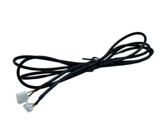
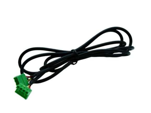
- Cables and switches for connecting to the LongBoard controller
- Resources and customer support to help set up and use the kit
What is a 4th axis?
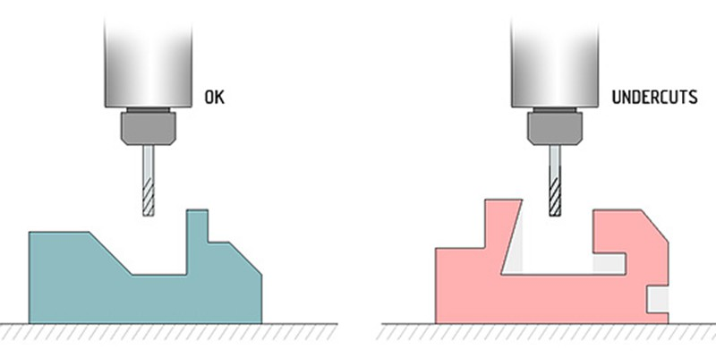
Most CNC routers like the LongMill use a 3-axis system, which consists of a X, Y, and Z linear motion system that is used to position bits and end mills. One of the limitations of a 3-axis system is the fact that 3-axis machines cannot make “undercuts” without flipping or material manually. Since the machine only can orient the bit vertically, there are limitations to the types of geometry it can carve.
To address these limitations, CNC machines can come with additional degrees of motion, typically including a 4th or even 5th axis. In the case for the LongMill, a rotary axis positioned along the X direction allows the machine to turn a part as the X and Z axis can move in sync as the material turns and rotates.
On a mechanical level, the 4th axis for the LongMill will come with a chuck to hold material as well as a series of bearings and pulleys connected to a stepper motor to rotate the material as the machine carves.
What can it be used for?
The best way to think about 4th axis is to look at it as a computer-controlled lathe. Projects that are best suited for using a 4th-axis include making table legs, chess pieces, threads, and other mostly cylindrical objects.


Who is it for?
At this current time, we are exploring the suitability of a rotary axis as examples of practical use are limited on the market. We’ve put a link to a survey at the end of the article to help us understand the use cases of a rotary axis by asking what the community is interested in creating!
Based on our research and experience, we feel that this is best suited for early adopters and people who are wanting to tinker with the technology and can accept that at this current time, it is quite primitive. There are quite a few steps to using this add-on and the learning curve involved that may not be intuitive to folks that are mostly familiar with the typical cartesian coordinate system. Additionally, there are a lot of new software features that need to be tested and created, and we expect software bugs in the initial development of the rotary axis that may be frustrating if it’s not expected in the early stages of this product.
Limitations
Software
By far the most important aspect of the viability of this project comes down to the software since a rotary axis is useless without being able to program it. At the current time, the number of software that supports 4th axis machining is limited and the ones that we feel are best suited for this application are paid. Some options include:
- Vectric VCarve Desktop, VCarve Pro, and Aspire ($349USD, $699USD, $1995USD)
- Fusion 360 ($1600/year)
- DeskProto Multi-Axis Edition (€249.00 for the hobbyist edition, €995.00 for commercial)
From our testing, Vectric’s software, in terms of functionality, ease of use, and price, is our recommended choice.
We won’t get into any specific details comparing the software today, but it’s likely that when we start to create documentation for 4th-axis programming, that it’ll be done using Vectric software.
Electronics
It’s also important to specify that with the current setup, this is not a true 4th axis. Rather, this setup uses the motor control from the Y-axis, disabling the linear motion from the two motors and redirecting the power to a single motor that controls the rotary axis. At this current stage, the plan is to provide hardware that allows for switching between rotary and linear motion by connecting directly to the control board.
While this seems like a big downside because the programming of true 4th axis is quite complicated and not supported by most hobby-level software.
Users who wish to explore true 4th-axis machining will need to use a more advanced control system and sending program to control the extra axis. We are working on creating electronics and software that will support this in the future, but we are not quite ready to share these details yet.
Hardware
Due to the size of the LongMill and the size of the rotary axis, users should expect to be able to cut materials up to 4.5 inches in diameter and roughly 10 inches less than the length of their X-axis. So 12×30 and 30×30 users would be able to do up to 20 inches in length and 48×30 users would be able to cut up to 38 inches in length.
The longer the material, the less stable the cutting is, since the material is only supported from each end of the machine with a chuck and headstock. Further testing will show practical speeds and feeds at different sizes.
Pricepoint
During the development of the project, we explored using either an off-the-shelf rotary axis option or designing one from scratch. It turned out that at this stage, it would be difficult to beat the cost of an off-the-shelf option purchased in bulk since if we were to design and manufacture it ourselves, the investment into design and the high volume of custom parts we’d need to produce would make it economically unviable.
Additionally, the off-the-shelf option appears to be quite well-made and good value, and ubiquitous enough that customers on a budget and willing to tinker may be able to source the same or similar option and use it for their machine, rather than buying it straight from us.
We’re estimating a landed unit cost for a pre-made unit in bulk will cost around $200. Additionally, the cables and electronic hardware required would add roughly another $15-20 to the unit cost. We also may need a precision fixturing plate that may cost around $100. Once applying a margin to account for things like development cost, customer support, shipping, resources, packaging, quality control, and everything else that we need to run a business, we’d estimate a price of around $500-700CAD per unit.
Additionally, users should budget to purchase software, as at this time we do not have a recommended free software option.
Next steps
Our next step is to determine the demand and viability of providing a rotary axis option to our user base. If we see enough demand, we can start to invest more time and resources in additional work and development such as:
- Sourcing parts to create a rotary axis kit
- Developing new features into gSender to add 4th-axis compatibility
- Design of hardware for mounting to the machine
- Resource development
- Stress and long-term testing
Our first step is to share this survey so that interested LongMill users can share their thoughts, wants, and opinions on what they want to see in a kit.
In terms of timeline, we expect to make decisions on the direction of this project by the end of January. Depending on demand, we’ll start taking pre-orders for the kit and start sourcing components. We expect the sourcing and manufacturing process to take around 2-3 months, which brings us to around April-May 2023 when users may start getting their rotary axis kits.
Survey
To participate in the survey, please click the link below. Your participation is greatly appreciated!