One of the most common questions we get from folks looking to order a LongMill is “What should I get with it?”. This article and video are designed to help you walk through everything you need.
The average order value for customers first purchasing a LongMill and accessories in the past 12 months is approximately $2850CAD or $2190USD, which means that for most customers, you can easily get a complete setup for under $3000. These numbers represent the total value of the order, which includes the machine, as well as most other accessories such as the software, router, endmills, a dust shoe, touch plate, and other items. You should allocate a few hundred dollars for other items that you may or may not have in your shop already, such as a bench, computer, and vacuum.
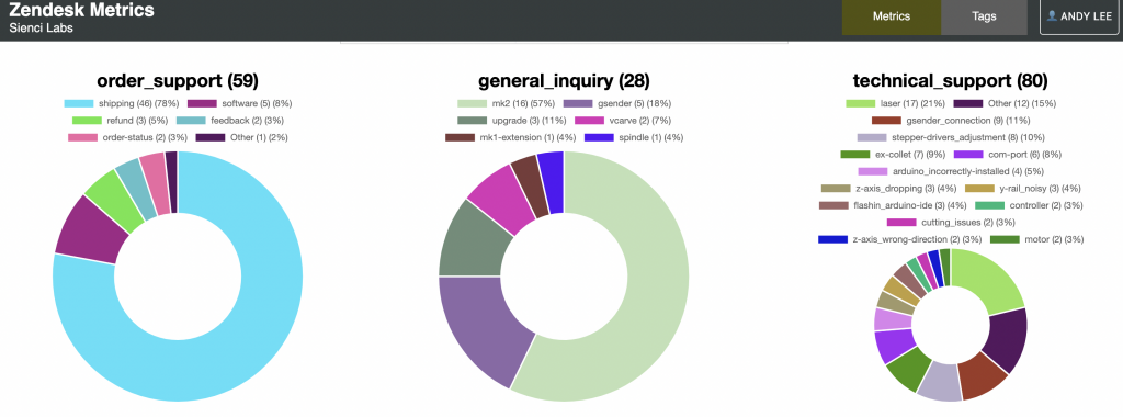
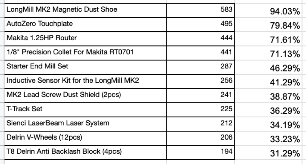
Here is the breakdown of the most popular items that customers order along with their LongMill by percentage.
The LongMill
If it’s your first time getting into hobby CNC, you might be a little intimidated by what you need to get started. This video is designed to cover everything you need to have in your shop.
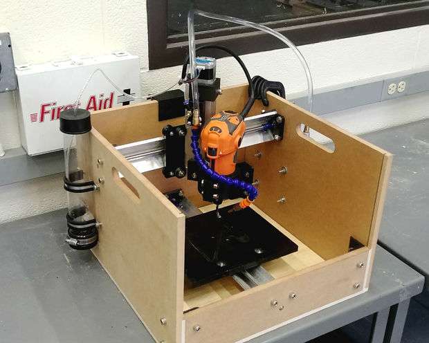
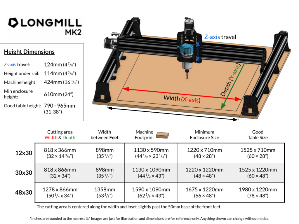
Your first, and largest purchase is going to be the machine itself. The LongMill Benchtop CNC is a capable option for hobbyists who are looking for a lot of functionality found on more expensive machines but in a more budget-friendly package. Depending on the size, you can get a LongMill for around $1800 to $2300CAD or around $1400USD to $2000USD, which makes it one of the least expensive options for the size.
While there are cheaper and more expensive machine options out there, we believe our specific machine is best suited for customers who:
- Are looking to do this as a hobby, with some interest in production and business work
- Need high-quality resources and support
- Willing to make a small compromise in cutting speed but still be able to produce the same type of work as more expensive machines
Our main goal as a company is to make CNC accessible to everyone. This comes down to a number of commitments to our customers and products:
- To make products that are affordable for the average hobbyist
- Provide resources, support, and instructions so that we can make sure our customers can be successful in using our products.
We feel that customers not only choose the LongMill because it is an affordable option, but because we created a helpful and supportive community around our products.
If you’re not sure what size to choose, we recommend considering the working areas of each version of the machine, and determining what size fits in your shop as well as can do the type of projects that you’re interested in doing.
Router or Spindle
The base LongMill kit does not come with a router, since we wanted to let customers choose which router they want to use with their machine. The LongMill can work with several different palm routers, but the one that is the most popular and the one we recommend is the Makita RT0701, as it’s inexpensive, readily available, and has more than enough power for general woodworking use. You can order this directly through us, or at most local hardware stores.
-
 Makita 1.25HP Router$165.00
The LongMill also can be retrofitted with an aftermarket spindle, and we provide 71 and 80mm router mounts for larger spindles, however, due to cost and complexity, we only recommend this upgrade to experienced customers. More information about routers and spindles can be found in our resources.

End Mills and Bits
You’ll also need to get some end mills and bits to start off your CNCing journey.
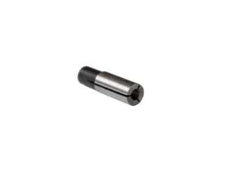
Assuming you have a Makita router, you’ll mostly be using ¼” shank tools, or if you get either the ¼” to ⅛” adapter, or the ⅛” Precision Collet, ⅛” shank tooling as well.

We provide dozens of different bit options and packs on our store. If you’re not sure what to get, we recommend checking out one of the End Mill Sets, such as the Signmakers Set and Machinist Set.
-
 Starter End Mill Set$60.00
 -
 Sign Maker End Mill Set$85.00
 -
 3D Carver End Mill Set$85.00
 -
 Machinists End Mill Set$90.00
If you’re starting out for the first time, I recommend the Starter End Mill Set, which comes with all of the bits that we think you’ll need and a collet adapter. The Starter End Mill set, which we recommend for first-time users, is about $45USD or $60CAD, and come with 9 different bits and accessories.
Prices for bits vary a lot, especially when you get into high-end tools, but for the average user, you should expect to pay a few dollars for smaller tooling, and up to around 20 dollars for a larger bit.
End Mills & Bits
All our bits are designed and tested specifically for CNC routers and spindles.
Bench
The last thing you must get for your CNC is a bench and spoiboard. This is just a large surface you can put your machine on. It should be noted that the surface should be as flat and strong as possible, since any flex or irregularity may show up in your cuts as well. Some people will make a bench from scratch, which can cost $100s of dollars, but even an old sturdy desk or dining room table can work as well.
Some different ideas and inspirations can be found in our resources.
You’ll also need a spoil board or wasteboard, which acts as a consumable surface for your projects to sit on. We recommend ¾” MDF, as its cheap, readily available, and dimensionally stable. You should be able to buy a 4×8 sheet and cut it into 2-3 wasteboards for about $60.
Computer and Software
There are two main pieces of software you’ll need with your CNC machine. First is the gcode sender. We build gSender as a feature-filled, powerful sender specifically for the LongMill. This program lets you send jobs, change settings, control your machine, and integrate with accessories like the touch plate and inductive sensors. Best of all, it’s completely free!
There are other gcode sending software, such as UGS and Openbuilds Control, but we think you should use gSender.
I recommend checking out our resources where we talk about different CNC software (Broll of scrolling through the resources, https://resources.sienci.com/view/lmk2-choosing-software/ or checking out our video on software to help you choose which software to get.
-
 Vectric VCarve Pro V12$896.00
 -
 Carveco Maker Subscription$0.00
 -
 Vectric VCarve Desktop V12$460.00
If you want to read about our thoughts on Free vs Paid software, we recommend reading our article on the topic.
Dust Collection
CNCing can be really messy, which makes dust collection an important part of your setup.
At our shop, we use a Rigid Shop Vac and Dust Deputy, both of which can be purchased for about $200. This sort of set up will be more than capable for hobby CNC dust collection use.
To help clean up dust while cutting, we have the Dust Shoe, a $60USD, $75CAD attachment which goes on the front of the machine to suck up dust while your job is cutting. This particular one works with the 2.5in hose from the Rigid Vac perfectly.

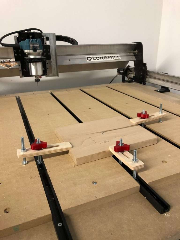
Work Holding
To keep parts from flying out while cutting, you’ll need some form of work holding. Certain methods, such as using screws or hot glue, are very inexpensive and are easy to use.
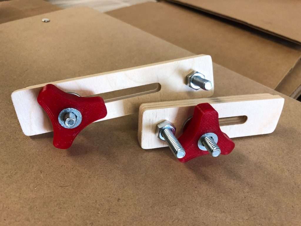
Some users will set up a t-track table on their wasteboard which allows you to use t-clamps and ¼” bolts to have a fast and adjustable system for workholding. A full set costs about $100USD or $125CAD.
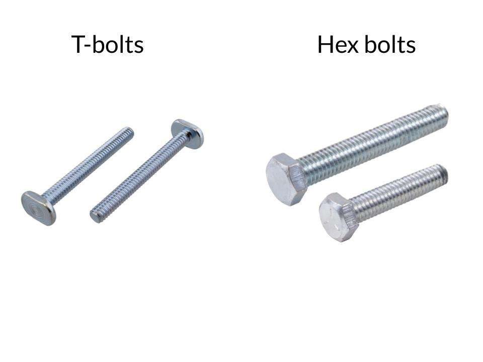
I should note what makes our t-tracks unique is that they use ¼”-20 bolts rather than t-bolts which are harder to find, so that you can buy different size bolts from the hardware store if you want to make your own t-clamps.
There are a lot of workholding options, so I recommend checking out our resources page for different options.
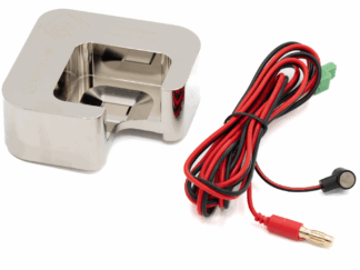
Touch Plate and Inductive Sensors
When starting your job, the LongMill needs to have a set origin point. You must choose a starting point for the machine to start from, and it will perform the movements sent by the computer from that point, in relation to the starting point.
The important thing is to setting the starting point. You can choose the starting point manually by just jogging the machine to the place you want to start and “Zeroing” the machine, but we’ve created the touch plate to help semi-automate the process.
We currently have a simple touch plate for around $30, and a more advanced AutoZero touch plate for around $100.
-
 AutoZero Touch Plate$120.00
 -
 Touch Plate$35.00
Additionally, you can add limit or homing switches to your machine. These are sensors that are set up at specific corners of your machine so that you can return the machine to a specific position over and over again (Broll of homing). For the LongMill, when you shut off your machine, it does not remember the specific position relative to itself, and so by having a specific homing position to return to, you can use this to reference the positions of the machine automatically. For example, if you want to set up a job in the same position over and over again, you can home your machine and find the origin of the part relative to the home position after you’ve shut your machine off.
You can get an inductive sensor kit for about $50-60 dollars from our store, however, we generally recommend this to only advanced users, since the setup and process for using it can be complicated, and we generally recommend users who are already familiar with their CNC machines to use it.

Other Accessories
The LongMill also is compatible with other accessories, like the Vortex Rotary Axis and LaserBeam add-ons that provide additional functionality. Over the past few years, we’ve developed these add-ons to plug and play with the LongMill. We plan, over time, to continue to create new add-ons and accessories that help our customers do more things.
-
 Vortex Rotary AxisPrice range: $110.00 through $720.00
For a full list of other add-ons and accessories you can get with your LongMill make sure to check out our add-ons section in our store (https://sienci.com/product-category/addons/mk2-addons/).
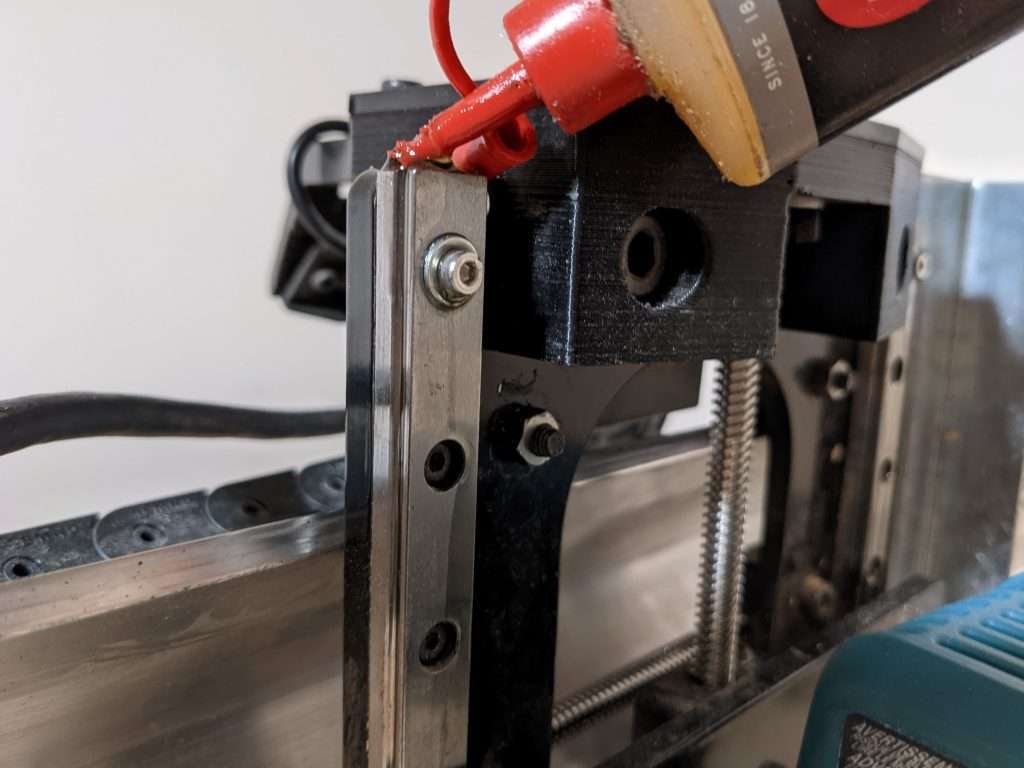
Maintenance Items
The LongMill requires some regular maintenance which is easy and straightforward to do. Recommended maintenance checks can be found in our resources.
There are only two consumable items, the Delrin Ant Backlash Blocks and Delrin V-Wheels which we recommend replacing every 1500-2000 hours, roughly once a year of regular use. Some customers choose to have them on hand just in case.
-
 T12 Delrin Anti-Backlash Block$11.00
 -
 T8 Delrin Anti-Backlash Block (4pcs)$18.00
 -
 Delrin V-Wheels (12pcs)$21.00
Conclusion
I hope this helps answer the “what should I get with my LongMill” question we get all of the time. If you have any other questions, please feel free to reach out!