Sienci Labs will be closed on Friday, April 3 for Easter weekend. Customer Support services will not be available. Orders can be placed as usual. Please use our online resources and help videos until the team is back on Monday, April 6. Dismiss
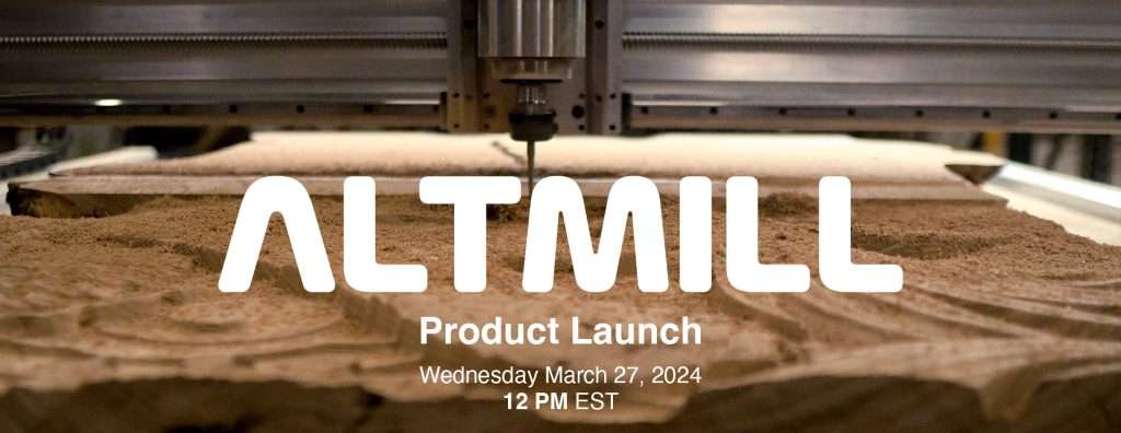
Hey everyone, we’re excited to share our launch date for the AltMill.
The AltMill will launch on Wednesday, March 27, 2024 at noon, EST. You can access the order page at https://sienci.com/product/altmill/ when the page goes live.
For more information about the AltMill project, please see https://sienci.com/altmill/. If you have any questions about the AltMill, please see the FAQ.
Pricing
The AltMill will come at a base price of $2950USD/$3990CAD, which includes the table legs.
Users can also purchase the Spindle and Dust Shoe Kit for an additional $515USD/$690CAD.
The first 50 machines
As noted in past updates, we’ve jumpstarted the process by starting production on the first 50 AltMills in December 2023. This allowed us to tackle some of the major unknowns/questions, such as:
What will it cost for us to make the AltMill?
How difficult will it be to manufacture certain critical parts, such as the rails, linear motion, and table that we were most concerned about?
What will our QA and assembly process look like?
What sort of performance and reliability should we expect from the AltMill.
As of the time of writing, the plan is to offer the first 50 machines directly to select users and for internal use before our “main batch”. The first batch of AltMills represents our trial-run for production and comes with a couple of you-should-knows, especially if you’re planning to be one of the users in this batch.
We also plan to collect comments and feedback from our first batch of AltMill users to improve the user experience and tackle any initial quirks and issues in the first part of the product launch.
Some parts are still in shipping and manufacturing, and we expect the first 50 machines to start shipping in May 2024.
The “main” batch
This is what we expect most users will be part of. We will begin taking pre-orders at the end of March. Please check www.sienci.com/altmill for more information and a link to the order page.
The goal for our first main batch is to build enough units to leverage economies of scale to make our relatively low price for the AltMill viable. This not only involves the unit cost of the machine, but the work and labour needed to build each batch of machines, which might include work done to set up tooling, packing stations, and the ordering of parts.
Please note that to place your order for the AltMill, the total amount must be paid to hold your place in our queue.* You may cancel your order at any time before your order ships for a full refund. Once your order is in the possession by the courier or arrives at your door, our standard store policies apply.
The number of machines we’ll make in the first batch is still undetermined and will be based on the number of orders we get at the beginning of the launch.
We expect the “main” batch to start shipping in July 2024. However, we will ship orders based on when they were placed, which means that if your machine is in the later part of the batch, you will receive your order accordingly after July 2024.
Future production
If you feel that pre-ordering the AltMill now isn’t right for you, you will eventually be able to order and have an AltMill ship to you in a shorter amount of time, just like the LongMill. However, when this will happen is dependent on when our production capacity can meet the demand for the product, which is unknown at this point.
The goals for the future production of the AltMill is as follows:
Have a reasonable lead time for us to build and ship AltMills. For us, two weeks or less from when we recieve an order to when it gets shipped is a pretty good number to hit, but the lower the lead time the better.
Produce larger numbers of machines to leverage economies of scale and either reduce the price of the AltMill or invest our increased profits into additional resource development and R&D that benefits the CNC industry
Take our learnings from this new product, especially in the production and QA side to create variations to the AltMill, such as a smaller, stouter, more rigid machine focused more on metal milling, or a larger 4×8 machine.
The size of future batches will be adjusted based on demand once our main batch has completed.
How to get updates
We will continue to share and provide updates in our Production Updates which are released at the start of each month at www.sienci.com/blog
Additionally, we will write order updates as we currently do with our other products at www.sienci.com/order-status
For the most reliable way to get news and updates, please sign up for our email mailing list.
The LaserBeam Vortex Riser mount is now available for purchase! It is a new add-on made for pairing with the Vortex. The Riser mount increases the z-axis height of your laser, providing significantly more room for LaserBeam focusing. Additionally, the product allows for more variation in LaserBeam mounting positions and is compatible with all versions of the Longmill router mounts. Made of premium zinc-coated steel, this rigid and durable mount is the perfect addition to take your rotary laser engraving to the next level.
This mount raises the Z height of your LaserBeam so you have more room to focus the lens. Each LaserBeam Vortex Mount order includes: 1 Zinc coated steel mount 5 M3-10 screws This product uses both the Laserbeam and Vortex systems. For more information on this product, you can view our resources here https://resources.sienci.com/view/lb-manual-vortex-riser-mount/ and…
We’ve prepared a detailed resource page and a video on assembling and attaching the Vortex Riser Mount to your LongMill. Also, feel free to check out the additional update to the LaserBeam resources that details how to use offsets in g-sender with the Vortex Riser Mount and a variety of different Sienci mounts.
If you’re interested in learning more about the LaserBeam and Vortex Riser mount, visit our product page below.
Hey everyone. We’re excited to share that the SLB will be launching on Dec 4, 2023. Chris and our development team have been going full bore in bug fixing, testing, and doing the final prep to get the SLB ready for production.
There are simply too many features and updates to share in one blog post, but we do have lots of different content and information you can check out to find out more about the SLB on the Youtube video, the product page, and our blog article, Next Big SLB Update .
Hey everyone. As you guys might have seen in the November update, we are now back working on the AltMill. If you have been following along with us since 2021, you might have heard about the AltMill project.
From 2021 and 2022, there were a couple of reasons and factors that led to us putting the AltMill project on the back burner, which included:
Not having enough space for the development and production of the machine in our current space
Continued need for development and focus on the current LongMill product
A general decision to focus on the lower end/hobby of the market at the time
However, in 2023, we’ve now established a strong process for the LongMill and with the move to the larger building, we feel like it’s a good time to put the AltMill project on the front burner again.
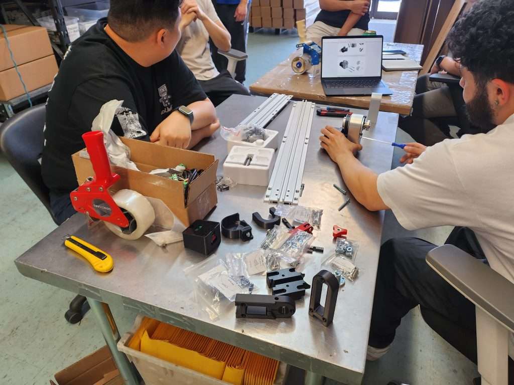
Things are already moving forward with the AltMill, as we currently have 50 machines in production for our first batch. We expect parts to start arriving for assembly in the next 2 months.
What is the AltMill?
#image_title
The AltMill is a CNC router that uses ball screws and linear guides and has a 4ft x 4ft working area. This addresses the two big “asks” we get from the LongMill community for a new machine, which is to:
Having a larger working area
Getting rid of v-wheels
The AltMill focuses on the same core ideas as the LongMill, which is:
Be simple, affordable, and easy to maintain
Come with excellent support
Be beginner friendly
The AltMill is aimed towards:
LongMill users who want to upgrade to a faster, larger, and more powerful machine
Hobbyist, prosumer, and small business owners who want to use for small scale production work
The AltMill is a completely new machine, with basically no parts shared between the LongMill, but users will find the process of running the machine to be almost identical.
Specifications
10,000mm/min rapids with closed-loop stepper motors
Higher rigidity with HG15 linear guides on all axis
Higher precision with 16mm ball screws on the X and Y, and 12mm ball screw on the Z axis
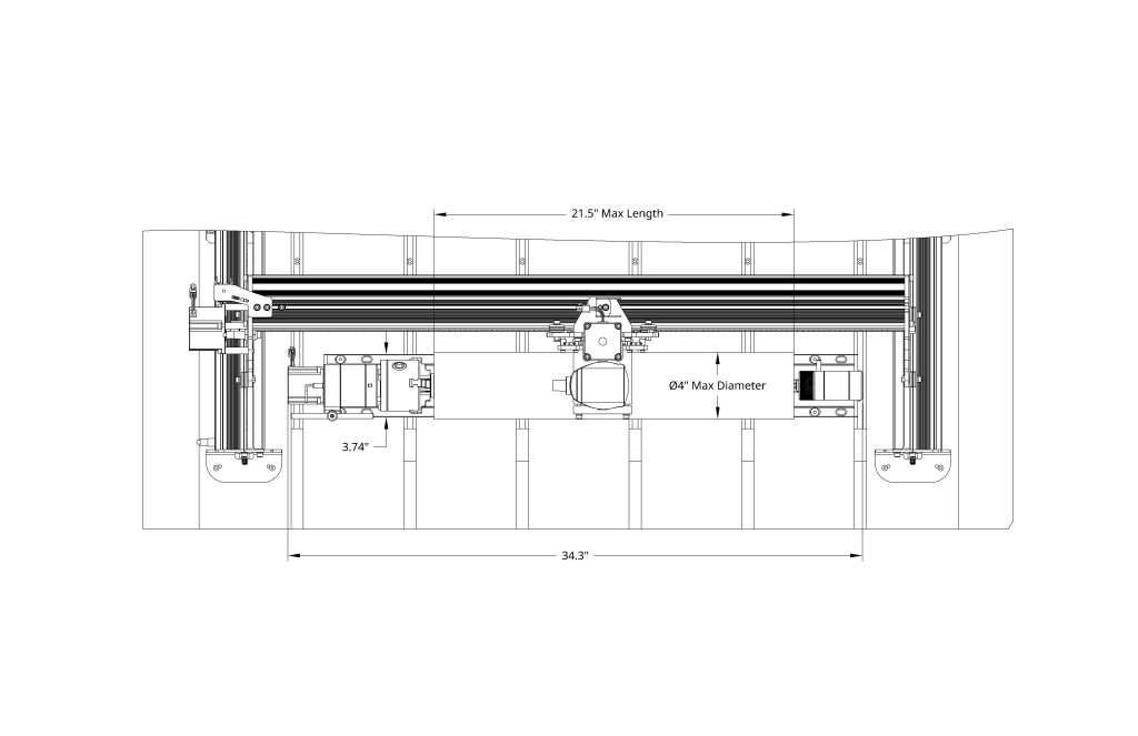
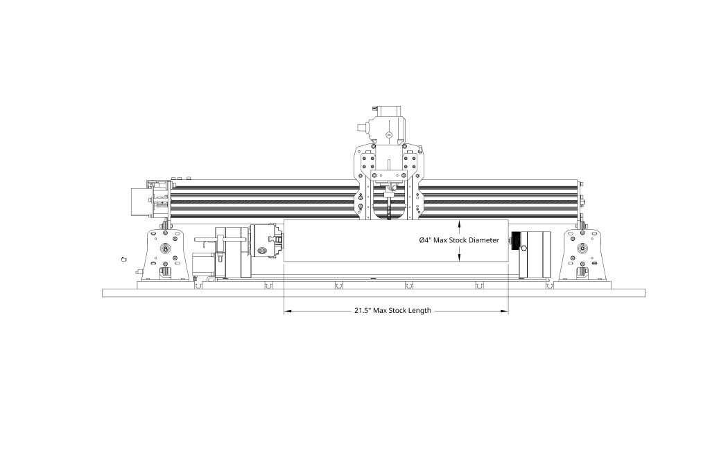
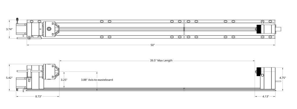
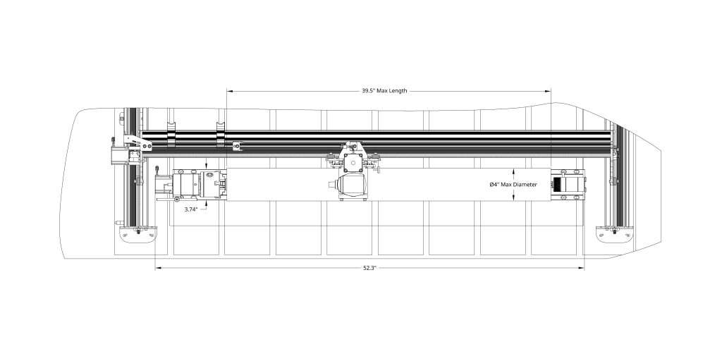
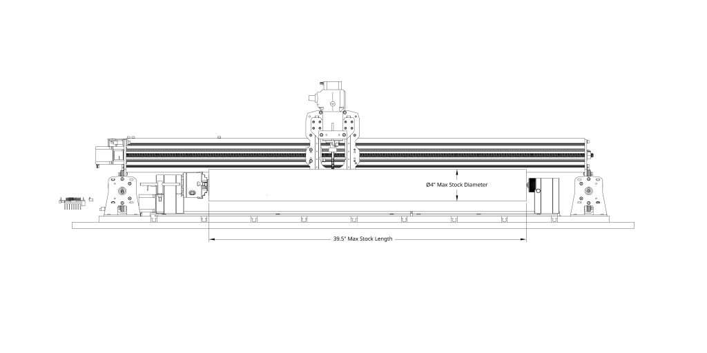
A working area of approximately 50″ x 50″ on the X and Y, and Z travel of approximately 6.5″ (with 4-5″ Z-clearance under gantry)
The original design used SBR16-type linear guides, which had a few advantages, with the primary one being that the height that the linear guide blocks sat met up with the exact same height as the ball screw nut, making it possible to mount everyone on the same plane like shown in the picture below. In this design, we mounted everything to machined plates.
We initially avoided using “square rail” guides because of their cost and need for more careful assembly, but with our new experience working with different manufacturing techniques and other factors such as finding a well-priced supplier for the components, using rails such as the HG15 family of parts became viable.
HGH15 components
One of the main manufacturing techniques we’ve come to understand better and use is extrusions. We’ve used this technique for making the LongMill rails, LaserBeam heatsinks, and the t-track clamping system, so we now have a better understanding of the tolerances we can achieve, and because extrusion allows us to space the components as we want to, we’re able to make more rigid structures while keeping the whole machine lighter. Additionally, we can add extra features to the rail and position components where we want.
Adding features like t-slot and locations on the ends to tap holes, we are able to reduce the number of parts needed and provide more freedom in mounting different things to the machine.
We use three main extrusions in the X, Y, and crossbracing of the table that keep the machine rigid while reducing the number of parts needed to put it together.
#image_title
Switching to an extrusion-based design also helps drastically to increase machine rigidity, without increasing weight. In the LongMill MK2, we were able to increase the rigidity of the X-axis beam while simultaneously decreasing moving mass by switching from a solid ‘open channel’ angle aluminum profile to a ‘closed channel’ extrusion. This makes for a significant strength-to-weight ratio improvement, which has been the case of the AltMill’s latest design revision as well.
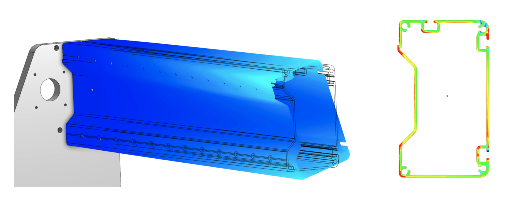
This is especially relevant for the case of the X-axis beam in most CNC routers, since tend to deal with very high torsion loads; twisting the beam. Closed channels (tube structures) are the most optimal shape for dealing with these loads, the closer a profile gets to becoming a perfectly round tube structure, the better it is at handling this load, and the better our machine will perform.
Simulation of an X-axis extrusion profile iteration, stress concentrations shown on right
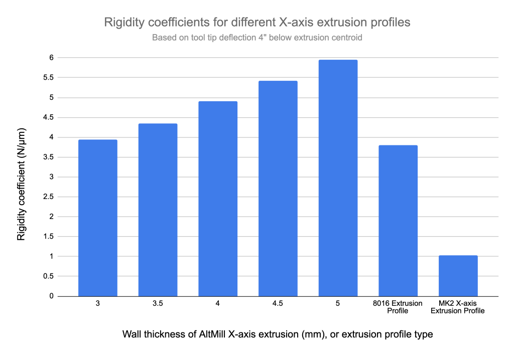
The new AltMill’s X-axis extrusion has also been sized to be much more robust than the LongMill’s X-axis extrusion. With better linear motion components, faster cutting speeds, and more utilization of higher-powered spindles it’s important to rebalance different components of the machine to ensure there are no weak points.
The rigidity coefficients of the AltMill’s X-axis extrusion at various wall thicknesses, compared to some other extrusions
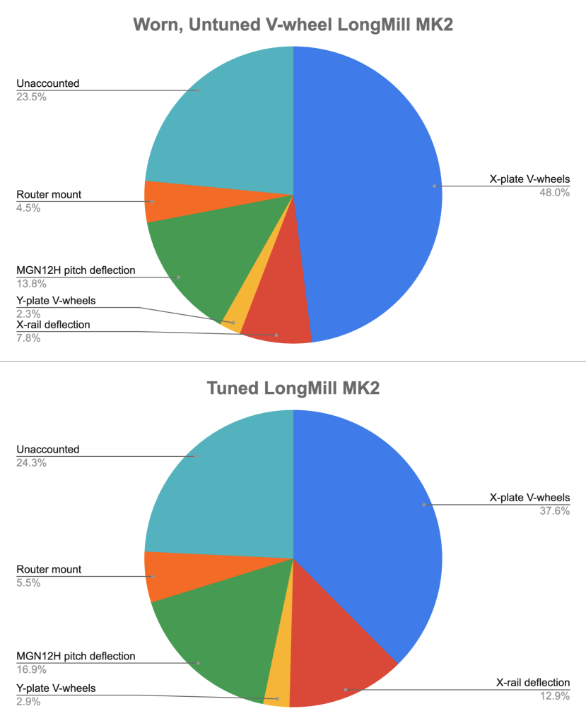
In a CNC router, you generally want to balance any deflection across all components evenly. Having a very rigid machine with a single weak component that causes it to perform poorly usually doesn’t make sense from an engineering or practical standpoint. Looking at a breakdown of various sources of deflection on the LongMill, we can see that with the exception of the V-wheels, the LongMill does a pretty good job of balancing this across major parts and sub-systems.
Since we’re now removing V-wheels from the equation in the AltMill, we now look towards some of the largest areas of deflection, since these will make up the bulk of deflection. Some of the more trivial areas such as the router mount, and deflection from the Z-axis linear bearings (MGN12 pitch deflection) can be addressed by better component selection, but the X-rail deflection stands out as an area where improvement will be needed at the design side.
Another, unrelated takeaway from looking at these charts is the variance of how much deflection the V-wheels on the X-axis contribute depending on their tuning and wear state. This can be problematic when you’ve set up your cutting parameters to fully utilize the rigidity of the LongMill (or any V-wheel machine), only to have them wear or fall out of tuning causing your rigidity to decrease and affect the quality of your project.
This isn’t to say that V-wheels aren’t more than adequate for the purposes of a hobby CNC router, but this matter becomes more of a concern when dealing with much more strenuous, repetitive projects where consistency over a long period of time is needed.
LongMill MK2 deflection breakdown by component/system
Another change not specific to the new design of the AltMill is the decision to pursue a closed-loop stepper motor system.
With regular stepper motors, the motor driver will instruct the motor to move some amount, and the controller will assume the motor has moved by that amount. If there’s nothing wrong with your machine, and you’re not running into anything that’s stopping your motor from moving, this almost always works fine.
When your motor driver instructs your motor to move some amount and it fails to move, or does not move the exact amount as requested, things get out of sync. This scenario is generally referred to as ‘losing steps’ since your stepper motor has skipped moving a few steps/increments and is not where it should be, or where the controller thinks it is. This is bad for a couple reasons such as:
The next toolpath your machine makes won’t be where it should be, typically meaning your cutting paths will appear ‘shifted’ in some direction
On a ‘moving gantry’ machine with two Y-axis motors, if one motor skips/loses steps, your X-axis will no longer be square with the Y-axis, and in serious cases you may damage parts or induce excess wear running it like this.
If the motors are unpowered (such as between jobs), bumping into the machine, or pulling one the router/spindle may move the motors causing them to lose position and create ‘shifts’ in your project the next time you run it.
Unlike a regular stepper motor, a closed-loop stepper motor will keep track of it’s position using a sensor known as an encoder. The sensor typically relays this position information back to the motor driver (ergo, closing the loop), to let it know if everything is in sync and motor is where it’s expected to be, or if something has gone wrong.
If something is off, the motor driver will correct for the difference, and move the motor’s position to wherever it should be. If it’s unable to, such as in the case of running into one of the travel limits, the motor driver will send an alarm signal to the controller to let it know that something has gone wrong, in order to salvage the project and prevent any sort of serious machine damage.
Closed-loop stepper motors also have some other neat benefits such as:
The ability to run at high speeds with reliability
More efficient operation (and resultantly with less heat)
In some cases, quieter operation
There have been a number of advances to hobby CNC technology and industrial technology in general that have made closed-loop steppers more affordable and easier to use. We’re excited to bring some of the new hardware into our designs.
Pricing
We expect the base price for the AltMill to start at $3600CAD/$2650USD, which comes with the mechanics, hardware, and electronics. This price does not include a spindle or router, but we anticipate that we’ll have something available at the time of shipping that would be suitable for the AltMill, such as a spindle package or our Sienci Router that is currently in development for around ($250 to 800CAD).
Because the AltMill uses a frame structure to ensure the whole machine is level and square, we are planning to have specially-made table legs that can be added to the machine to allow the AltMill to be its own standalone bench, eliminating the need for users to need to build a bench like the LongMill. We expect this addition to come as a kit for around $150-300.
Other accessories (and necessities) such as T-tracks and dust shoes will be available specific to the AltMill near the time of launch as well. Most accessories that currently exist for the LongMill system of CNC routers will be compatible – this includes things like the LaserBeam, Vortex Rotary Axis, and any of the future add-ons that pair with the upcoming SuperLongBoard controller.
Users will need to provide a wasteboard (3/4″ MDF) to be mounted on top of the machine.
Production
The AltMill is already in production and we expect the first batch of parts to arrive at the end of December. We expect to have our first working machine in February. We are ordering enough parts to build 55 AltMills and expect to yield a minimum of 50 units in this batch. We expect to have units start shipping in March or April.
50 units is a pretty small batch to start with at our scale, but since we’re not sure how much demand we’ll see for the product, we’ve decided to keep the number pretty low. I think even if we only sold 50 machines, since they are fairly simple and use a lot of off-the-shelf parts, we can keep them supported on a small scale as well. My expectation in the long run however is to be able to ship and sell around 1000-2000 AltMills per year.
Ordering
We expect to start pre-orders sooner or later based on the demand for this machine. Basically…
If people want to give us their money right away and pre-order now, we will set things up so that can happen. This would be the ideal situation since it would be less risky to invest in this new product for us financially, but be the most uncertain for the customer on when they would be getting their machines.
We launch the pre-order when we have a fully working machine so that people can see what it looks like and have more confidence in a specific launch date.
We start to sell and ship once we get all of the parts in and the design is complete. There would be a short wait time as we build and pack machines.
Let us know what you think. If you’re interested in ordering an AltMill now, please fill out the survey below.
FAQ
Technically not an FAQ, but more of an anticipated FAQ…
Will the AltMill be compatible with a spindle?
Yes, we actually believe most customers will want to default to a spindle to take advantage of the AltMill’s higher speed and rigidity. We will be working on a spindle or higher-powered router option at the time of shipping that will be able to be used with the AltMill.
Can I upgrade my LongMill to an AltMill?
No. Because this is a completely redesigned machine, there will be little to no parts shared between the two platforms.
I want to pre-order an AltMill right away. Do I need to put down a deposit?
At the current time, we are planning to ask customers to pay the full price of the machine upfront once we decide to open up pre-orders. You may change or cancel your order at any time before your machine ships.
Do I need to assemble the AltMill?
The major parts of the AltMill such as the X-axis rail and Y-axis rails will come pre-assembled, but will have some basic assembly to help keep shipping costs low. We expect set up for an AltMill to take around 2-4 hours with a basic set of tools.
Will there be a 4×8 AltMill?
At this time, and for the near future we will only be offering a 4×4 AltMill. It’s possible we may look into creating a 4×8 variant of the AltMill much later on.
Will there be an ATC (auto tool change) spindle/system for the AltMill?
It’s not in our immediate plans to offer an ATC system for the AltMill, however, this is something that could be possible much later on as we continue development on the Sienci Router project. In the short term, it will likely be possible to integrate such a system on your own since the AltMill’s controller will run grblHAL firmware which supports more advanced tool-changing features needed for these systems to function.
Will I need to connect a computer to control the AltMill?
The short answer is, yes. The AltMill will need to be tethered to a computer at the time of launch. That being said, some of the development to move the computer onto the board or for us to provide a separate computer module applies that we’re working on with the SuperLongBoard for the LongMill, so we expect at some point, we’ll have a more integrated system for the AltMill. Currently the options we are assessing are expected to cost around $200-300.
Hey everyone! We have a small change we’ve made to one of the key components to the LongMill that we’ll start shipping for machines going out in the next few weeks.
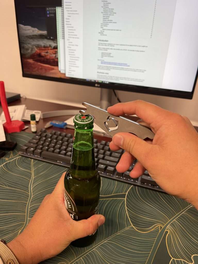
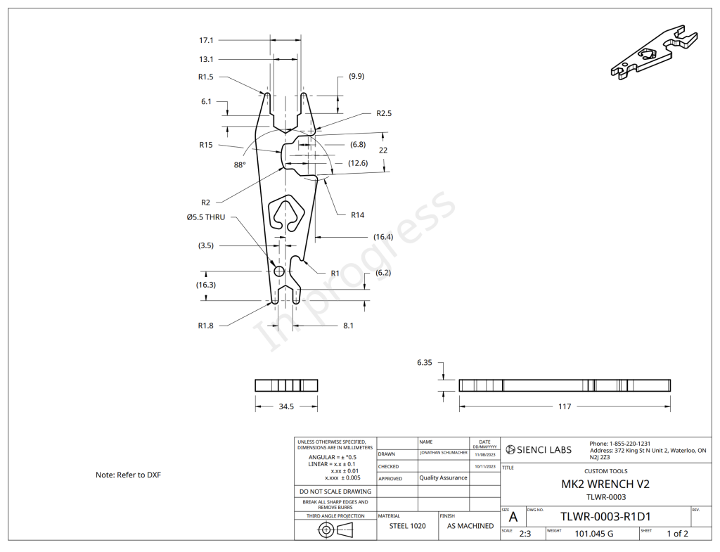
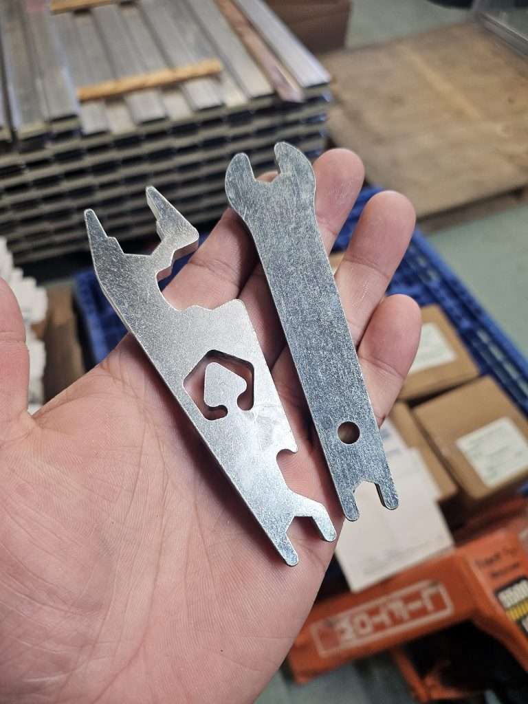
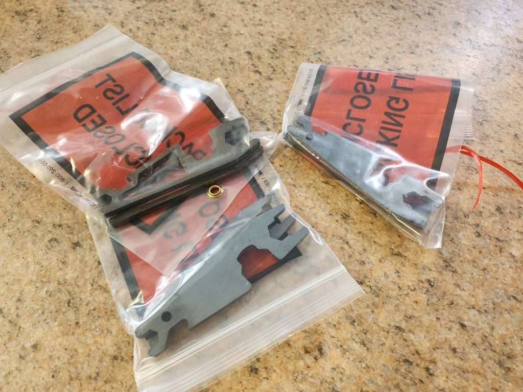
For the uninitiated, every LongMill comes with a “Maintenence Wrench”. We include this in every LongMill kit as a tool for assembling the machine and adjusting things like the ACME locking nuts and eccentric nuts. Every LongMill comes with a wrench and a set of Allen keys for assembling the machine.
Functionally, the new wrench remains the same but with the biggest difference being:
Adapted to fit new ACME locking nut hardware
More ergonomic shape
And most importantly… a bottle opener!
We hope that small improvements like this make a big difference in your enjoyment of the LongMill.
Also, it looks like the hanging hole got missed…but should still be functional the way it is, but we’ll have to fix that in the next batch.
New wrench on the left, old (V1) one on the right. V2 not shown
Hi everyone, Chris here. It’s great to be speaking with y’all again, it’s not often I get around to writing blog posts since I tend to be more behind the curtain on the tech development we do here at Sienci. As Andy mentioned in his November Production Update post, there’s a lot to update on so I’ll spread as many juicy details as I can. We’re now at over 400 people interested in buying the new SLB system we’ve been working very hard at so thank you for your support! It’s very clear that our community is very excited about this massive upgrade to the LongMill and for the future of the hobby CNC industry.
There’s also a video I filmed which you can feel free to watch if you prefer to see more of my face 🙂
Recap
Let’s start with a quick refresher about how the SLB came to be Sienci’s biggest project to-date.
As many of you know, Sienci Labs has historically been built up by our mechanical solutions – an expected direction seeing as myself and Andy co-founded the company while studying Mechanical Engineering. Our goal with Sienci was always to take advanced, industry technology and try to find a way to simplify it in ways that made it less expensive and easier to use so that everyone could have access to making complex things at home. We feel like that goal of price-point and ease-of-access is something we’ve been proud and successful at to-date with our big projects like the LongMill turned LongMill MK2 CNC, LaserBeam laser system, Vortex rotary axis, AutoZero touch plate, and our unique MK2 Magnetic Dust Shoe.
What’s been clear to us since the start though is that the CNC experience won’t be able to be improved with mechanics alone. Most hobby CNC communities have quirks with their machines, but once those quirks are understood the majority of confusion comes from everything else you see day-to-day when you use it: designing projects, tool selection, feeds and speeds, machine control, and reliable cutting. This is why we started working hard on non-mechanical solutions that we’re also very proud of like gSender for open-source CNC control, our in-house feeds and speeds charts, our expansive resources for learning and understanding CNC, ever-growing roster of tutorial videos, and now the SLB.
Why the SLB?
The SuperLongBoard is a next-generation CNC control board we’ve been dreaming of making for years now and is getting closer to completion. We believe that at this current stage, integrating smarter, more reliable, and more capable CNC control electronics will make the biggest improvement to the CNC experience. If you look at options on the market there’s been a large divide between the capabilities and reliability of the typical hobby CNC boards in the $40-$200 price range and the far more expensive, semi-industrial options that can reach the several-hundred-dollar range to over $1000. With chips getting more powerful and lower cost, we thought that gap in ability could be reduced while still staying in the lower price range by making a board with those new technologies. We knew this was going to be a big challenge – there are reasons why it’s typically easier to up-sell older technologies than it is to develop new ones – but we felt strongly in our decision. We felt that creating a new, improved, and unique solution could bring new innovation to the market to benefit everyone by reducing barriers to entry, keeping the industry progressing, and making more reliable and capable CNCs at lower price-points.
Working alongside Andrew and his team at Expatria Technologies, and building off of Terje Io’s amazing grblHAL project, all these tools need to work hand-in-hand so we can set our sights on resolving two major areas that we think hobby CNCs could benefit from:
Reliability: this is such a broad topic to solve, but it can be more-or less divided into a couple categories.
Board wiring and protections: designing a board with proper grounding and plenty of voltage protection and isolation takes a lot of time and experience but is needed to shelter the electronics from CNCing – an electrically ‘noisy’ environment from all the moving motors and static electricity buildup from cutting and vacuuming materials
USB protocol: this is implemented in firmware and grblHAL comes with far more checks with data communication mechanisms in place to guarantee delivery over USB and know when to resend lost information
Backup Communications: adding Ethernet on top of grblHAL’s already robust USB implementation isn’t necessary but having an alternate communication method to turn to is always a great option if you’re ever experiencing problems with the primary style – an onboard SD card also gives you that flexibility
Processor speed: a slower processor can’t buffer as much information when dealing with short and complex movements, meaning better chips can reduce the chance of errors popping up
Room for growth & “Wow factor”
Motor drivers: the same stepper motor controlled by different motor drivers can see notably better performance with all else being equal – so why not upgrade to newer-age drivers to get better speed with less motor noise out of the same CNC
Smarter CNC: having the CNC better tell you when something has gone wrong, automatically fix a problem for you, or make one of your existing processes easier creates far less room for error
More control options: there are typically specific limitations on what a CNC can do, so why not expand it’s options to support all commonly used CNC accessories plus leave space for even more customizable outputs. This can include things like independent Macros buttons, independent Spindle and Laser control, Modbus over RS485 for more closed-loop VFD control, tool length sensor support, ring and rail lights, door sensor, CANBUS, CNC pendant options to control the machine more easily, adapting to plasma cutting, and more
Multi-axis control: benefits those who have started to dive into cutting rotary projects to create ornate, fully 3D projects on their CNC and want either a simpler transition between cutting styles or are interested in full 4-axis cutting
Onboard computer: if you’ve ever run into problems with a Windows update, USB port falling asleep, or having hardware too underpowered to run your CNC, these problems can all be solved with a dedicated, purpose-built, and built-in computing solution running something like gSender onboard
We think we can address most of these aspects with the SLB at the time it ships so it can play a part of the next big step in hobby CNC technology. It’s advanced electronics and software will bring not just new features and functionality to the LongMill, but at a price point that we believe will be affordable for hobbyists. With it being a Sienci project, it can also guarantee that the SLB will be backward compatible with ALL LONGMILL CNC MACHINES OF ALL GENERATIONS, which means that users can upgrade their machine’s capabilities by simply replacing the controller. It will also support all our current plug-in add-ons. We also plan, just like with gSender, to make our board well documented and able to be adapted to many other CNC form-factors when we start to work through rolling it out in production.
How it’s coming along
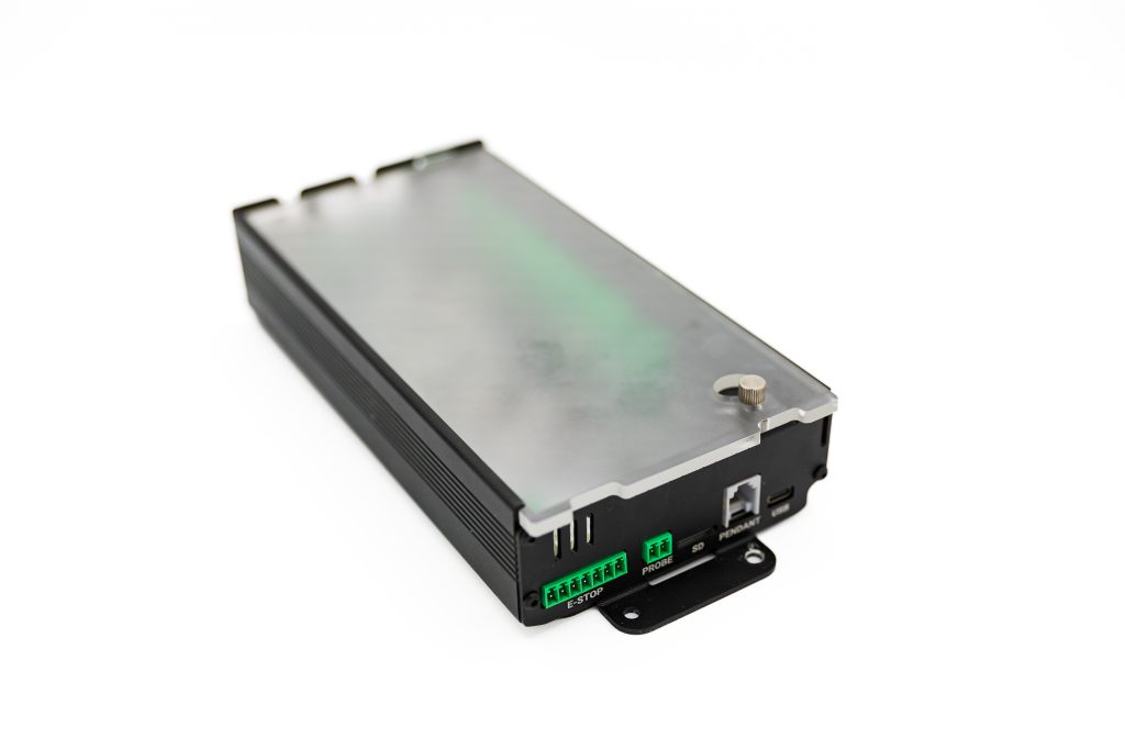
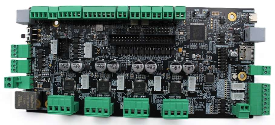
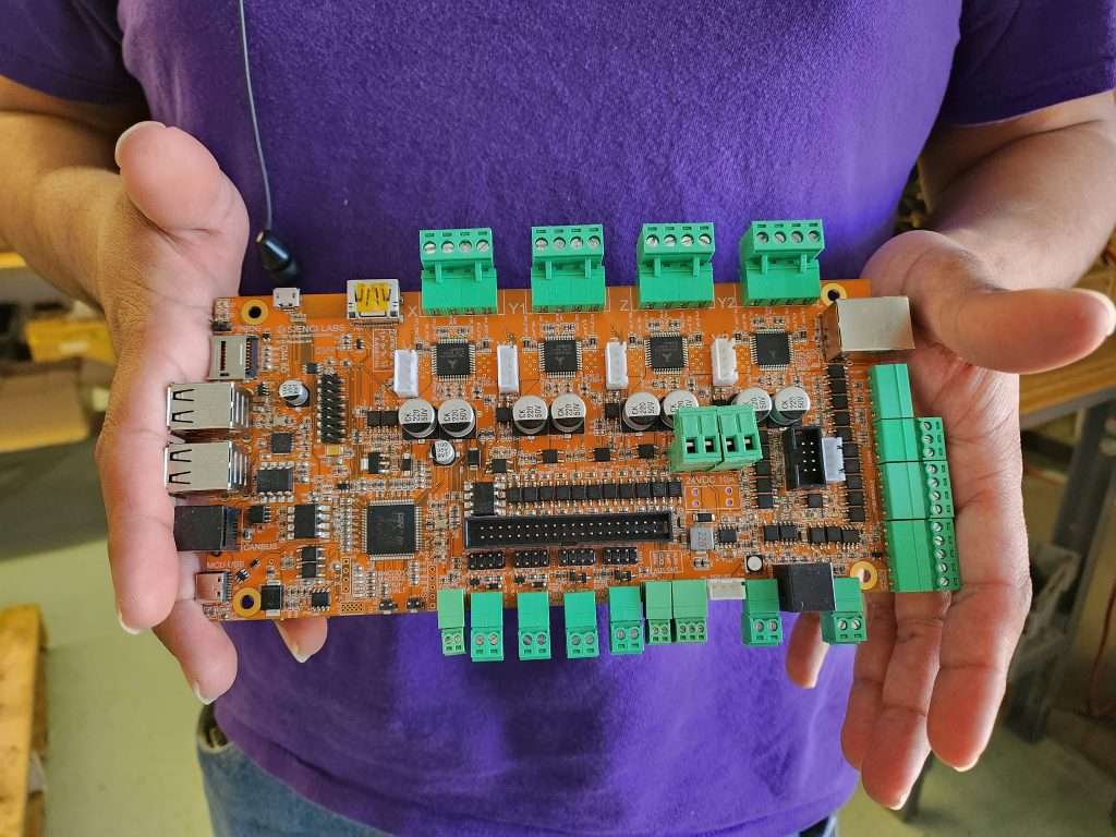
Very well! Since Andy’s last update, our SLB team has been working hard to prioritize checking the functionality of the physical circuitry on the V2 prototype board are we’re now feeling confident that the following circuity is good to go:
Newest version of the SLB (V2)
24V 12.5A brick power supply input with power switch (no more power over computer USB)
External, detachable E-stop with light, controller feedback, plus 3 customizable buttons
More reliable implementation of serial communication over USB-C (no drivers needed) as well as Ethernet
4 higher-end, independent motor drivers rated for 2.8A RMS (TMC2660C, higher efficiency, less noise and resonance)
RGB Machine status LED
‘Contact’ style touch plate input
4 independent limit switches with two connector styles and 5V or 24V output
Coolant digital output set via M8 and M9 commands (5V 40mA)
Independent rotary axis support with dedicated limit switch
Tool length sensor input for easier tool changes
Modbus over RS485 to control spindles and other accessories with two connector styles, terminal breakout and CAT3 cable with RJ11-6C/RJ25 and supports daisy-chaining
Very dust resilient enclosure with quick assembly
Many status LEDs for troubleshooting
Tons of opto-coupling for optimal protection against incorrect wiring and electrical noise
Less heavy boards with less fragile components should lead to lower failure rate
Extendable RGB LED ring light and rail strip output
4 customizable outputs to external circuits, controllable via M62/64/63/65, M7/M9, M8/M9, and M3/M5 (2 SSR pin shorting and 2 relay/solenoid/motor driving)
SD card to store onboard information and possible g-code file overflow (min 512MB)
Door sensor for input to pause cutting
Special CANBUS for pendant communication
Extra breakout IO to access spare MCU pins and other alternate outputs
ADC input for future sensor input
Communication connections (e.g. Rx and Tx) available for future control via external controller / pendant
These could still change a little on our way to production but I’m very confident that this will give an accurate image of what the SLB will be capable of. The gray items on the list might not be ready at the time of launch but the great news is that we have verified all their circuitry and put them on the board so all that’d be missing is a firmware update we plan to put out after shipping boards to enable those features as well.
The main items absent from the list are twofold:
Firstly, though we aimed for the V2 board to be our second and last prototype, we did find some areas that we wanted to tweak. These were: changing the Spindle 0-10V output back to 5V PWM to support the new spindle we’re working on, changing the Laser PWM and Flood output circuitry to deliver a signal that’s more in-line with the previous LongBoard, tweaking the RGB LED driver buffer, fixing some onboard status LEDs that were floating, and adding some more EMI improvements. Most of these changes are quite small, but we decided that getting a V3 prototype made will help us feel confident in finalizing the design for production. This is a hard decision as it’s likely going to add another 1 month to our board release timeline, but we really wanted to be sure to support one of the key features we wanted the board to have “Independant 5V PWM and EN Spindle and Laser control set via M3, M4, M5, and S g-code commands, plus SpinDir“. The V3 design should be sent out to get made in the next week and should now lock-down the full SLB design. While we wait for it to arrive we’ll be focusing fully on testing and firmware improvements.
Secondly, for those who might not have been following Andy’s production updates, we’d originally envisioned the SLB as being a system of two different parts working together. The first being the board itself, containing all of the core CNC functionality controlling motors and handling g-code, and second being an optional onboard compute module that would act to replace a computer or laptop and instead be integrated. Users could connect a keyboard, mouse, and monitor to control all functions of the machine directly through the SLB. This was very exciting to us given the considerably low price of the compute module over a computer, around $40-80 dollars plus the cost of the monitor, keyboard, and mouse, as well as the extra speed, user experience, and reliability of an onboard system.
In our extended tests with this idea in mind, we weren’t finding the success we’d hoped in creating a seamless user experience with this solution. Despite trying many Linux kernels, drivers, GPU acceleration, and bringing many more efficiencies to gSender, the Broadcom and Rockwell-based processors used on smaller compute modules were not powerful enough to accommodate the visualization of g-code directly onboard. This also meant they didn’t have extra headroom if in the future we wanted to implement other features such as having a camera monitoring system or other sensor inputs. With many months delay trying to chip away at a resolution we decided to split the development of SLB back into its two parts; prioritize improving the baseline machine performance first so CNCers don’t have to wait any longer for the SLB to make better machines, and strip out all the on-board connectors and switch to a higher-power off-board solution that we’ll implement at a later stage. This will mean anyone could still upgrade at a later date. Higher-power Fanless PCs will cost more, from our initial budget of around $80CAD/60USD for the compute module, to somewhere around $100-$200USD depending on the specs and configuration, but would ensure a smooth and seamless experience as well as provide headroom for future applications.
To summarize, we decided to take the concept of the onboard computer and divide and conquer on it at a later date. It would’ve been really cool to have a fully integrated system but it kept pushing our board delivery back further and we felt it would benefit everyone if we just pushed ahead on the other features that will all still bring great benefit to the CNC experience. This means that users will still need to connect their computers to the board to control their machines when the first batch of SLBs release, but should still see drastic improvement.
To-date, SLB development costs have tallied to more than $300k, making it easily our most expensive project to-date if you don’t count gSender which is I’d guess is around $500k at this point. These costs are pretty standard and have mostly come from paying salaries to do in-depth research on board infrastructure options, decisions on features that CNCers would like, designing robust PCBs, lots of custom firmware development, and testing. The new board uses a large number of components, adding to the challenge and complexity in manufacturing, but this was expected and we’re working through it. We feel confident that we’ve done something useful here and we’re excited to see the interest in the SLB on launch and continue moving development forward.
grblHAL support in gSender
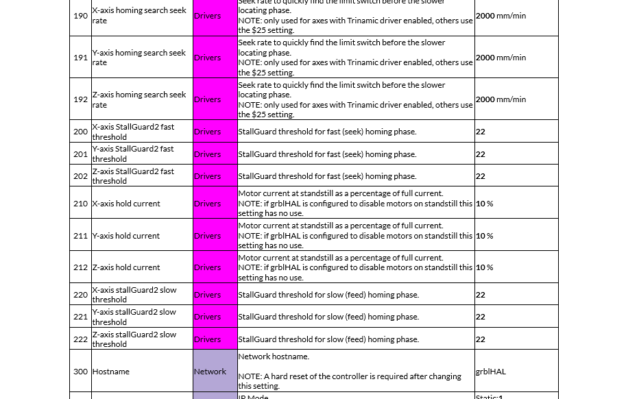
Another big effort we’re having to undertake to support the SLB has been with gSender. Though grblHAL has “grbl” in the name, it might as well be a completely new firmware with all the new work that our development team has had to put in so far to make a seamless CNC control experience and UI. Since grblHAL is such a new firmware on the hobby CNC scene, it’s still growing and not widely adapted, and we want to help change that. There’s so much documentation that has already been made but there’s also a lot more we have to figure out. We’ve been working on an all-new firmware flashing utility for the new board, and had to build in a lot of modularity so gSender can be compatible with old and new boards alike
Look at an example of all these new EEPROM settings!
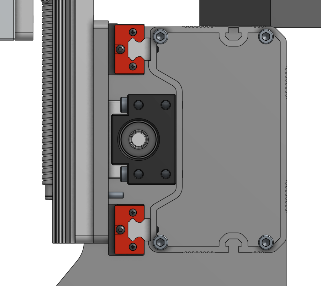
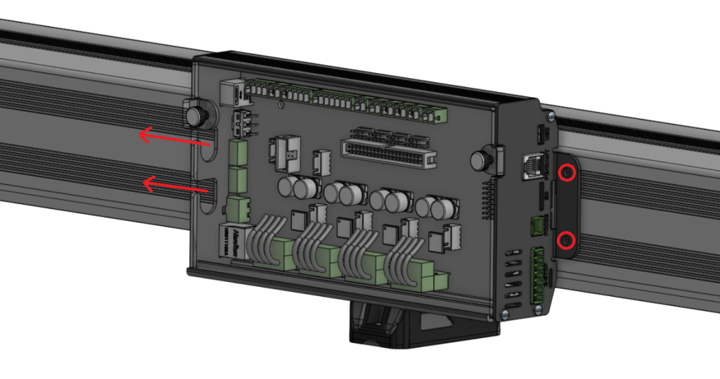
Iteration on the SLB enclosure I think is coming along well, the design is now pretty much locked in 🙂
Back in April I put out a post on our Forum with the leading design we had at the time to get peoples feedback on what they thought (https://forum.sienci.com/t/official-call-for-feedback-on-new-board-in-development/8519) and the results were positive but still mixed. I wanted to take a new approach to the enclosure design to accommodate all the new plugs without them all being exposed, as well as improve cable management on the LongMill in particular. Though many people were on board, many still expressed concern with my idea behind mounting the board to the Y-axis rail due to their fear of dust, vibration, or accommodating enclosures.
After going through way more iterations internally, this is now our revised design which I feel much more confident will suit everyone’s needs:
#image_title
The main perks of this enclosure is it’s mounting versatility and wire management. With this new setup, anything that you’d expect to have more common access to faces toward the front and all other wires can be routed out the rear. The RGB status LED will be visible through the faceplate put the panel will also be easily removable for troubleshooting or servicing. All the components on the board face upwards so everything is accessible and the board has been tested to run very cool so even in hot environments and with the bit of venting we’ve added in we expect everything to operate as normal.
Rail mounting bracket
The rail mounting is also a separate piece that can be used or not. This gives versatility to mount the SLB on any surface (rail, vertical, or horizontal) with 2 or 4 screws. We’ve already begun production of the parts and should be getting them in Nov-Dec.
E-stop Design
This is also mostly completed, just waiting for some last few checks. You’ll notice on the earlier feature list that we wanted to move away from the 3 buttons attached directly to our board. This is because there was feedback that people didn’t tend to use the existing buttons because of their fixed function, and when people mounted their board out of the way they couldn’t access the buttons anyway. We wanted to fix this by making the buttons separate and customizable, and this lead to a new E-stop design with 3 other customizable buttons integrated into it! Now you’ll have the freedom to have 3 physical buttons perform a myriad of custom functions to suit your workflow right next to your E-stop.
New E-stop design
Beta Testing progress
As we’re turning the corner on finalizing the board design and implementing our initial set of firmware features, our main goal over the next month will be: test, test, test! We’re now in Phase 2 of Beta testing where our main goal is to make sure that all our new features play nicely with each other, since we already know they work well in isolation.
We currently have 3 boards with testers and 2 dedicated machines in our own shop running CNC jobs every chance we can get and have already found unique situations that cause problems which we can now work toward resolving. This also involves comparisons between the old and new board and real-life durability and performance testing. One example is Ian’s Onefinity where his former setup used our original Longboard and with the SLB he’s seen drastically reduced noise and nearly doubled movement speeds. This hasn’t been as drastic for our other testers but we’re also already noticing some of the stability and perks that the SLB has to offer. Once the batch of V3 boards arrive, the plan will be to redistribute them as well as contact a new wave of testers to complete one final round of feedback. Some people we reach out to will be those with persistent and existing EMI and disconnection problems to see if the SLB is able to resolve those issues. At that point we expect to feel confident in the performance and features we can promise with the board that we can prepare for release.
Here’s a video from Andy’s last post of us testing the new programmable macro buttons. These allow you to program a specific code or function to 3 unique buttons, rather than just start, pause, and stop, which is hardwired into the current control board. In this case, it’s being used to move the machine to a specific position to assist with getting the machine out of the way for changing tools and materials.
The pricing is likely to be refined as we’ve made new decisions and near production, but I think no matter how you slice it you’ll be able to expect that the SuperLongBoard will be giving you every bang for your buck.
As far as timeline, many followers of this project would know that we’ve had to push our originally anticipated late-summer, early-fall launch. We’ll be putting out another update soon on the roll-out strategy we have in mind moving forward because we want to give people a guarantee to be in line for the SLB before Christmas, so stay tuned to hear more about that. You can get a glimpse of what some of the steps will be with the roll-out in Andy’s original post as well under “What’s Next?”.
As far as ongoing project schedule, much of it has been laid out in the sections above which I’ll try to summarize here:
Last tweaks will be made in the next week to start a batch of V3 SLB prototypes
Firmware, Beta testing, and gSender support will continue over the coming month while we wait for the V3s to arrive
SLB Enclosure and E-stop designs should also become finalized and be ready for production in the next month or so
Once V3s arrive, final checks can be made to feel confident about the circuit design and begin board production
Phase 3 of Beta testing will continue to refine Firmware and gSender support while all other production is underway
I’d say that this means the boards won’t be ready to ship in December / Christmas and are instead more likely to be able to ship around Feb-March. The first major steps we took until June 2023 involved much of the initial product churn that we expected to see, though with delays in board prototypes and unexpected difficulty interfacing with the drivers we lost about 2 additional months. Add to that the outcome of the compute module testing meant that we had to pull out a lot of components for a full redesign between V1 and V2 and now we have to address some of the missed items between V2 and V3. This is the reality of developing such a complex product and is why we now feel much more confident with the recent testing and steps that we’ve taken that the completion of the SLB for launch is just around the corner 😀
Thanks
Thanks for sticking along for the ride on this big update, I hope it answers most of your questions on where the SLB is currently at and gets you excited about what’s to come. I expect the SLB to be very unique in it’s abilities to exceed the capabilities of many hobby CNC boards, perfect even for the DIY hobby CNCer for all it’s additional IO, and still have many more plans for it in the future. Of course it’ll be an Open-source design so hopefully all this time and effort that our team has put in will be able to return to the community and benefit other efforts toward easier CNCs.
Leave any comments you have that I missed and I’ll try to answer them. As I mentioned I don’t tend to put out updates because I’m a very slow writer but I’ll ensure to keep Andy in the loop as progress continues so he can update y’all as things keep moving forward. Just remember to read the Production Updates!
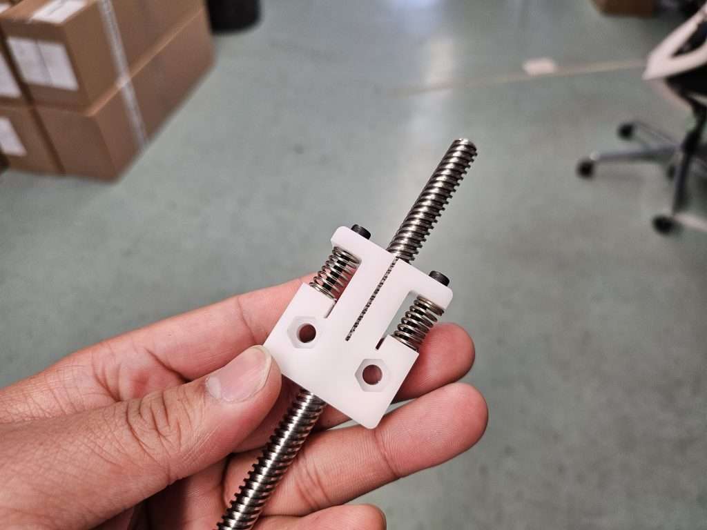
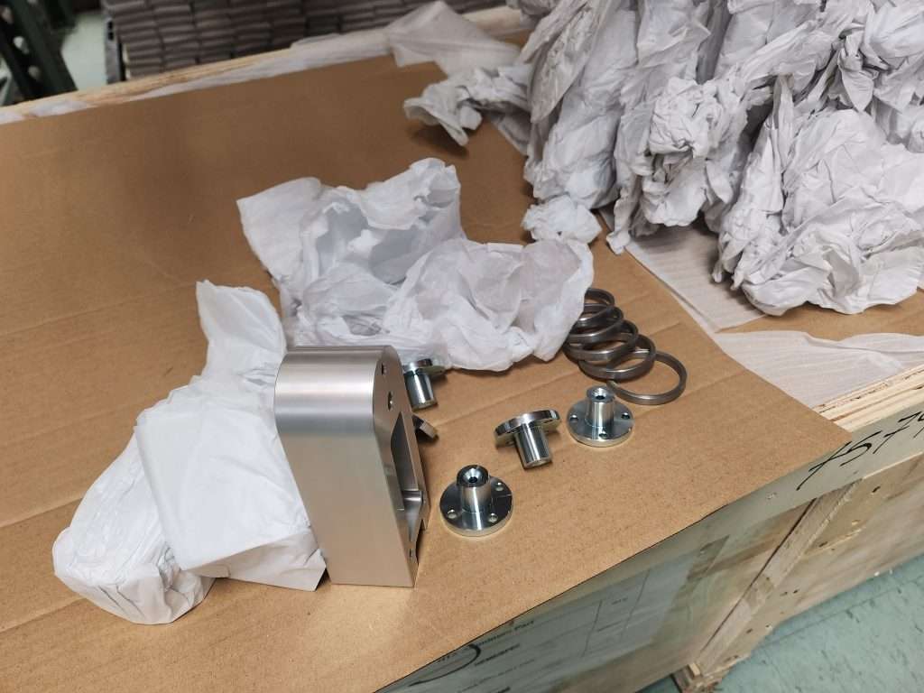
Hi everyone, I’m excited to share a small development, the Spring Loaded Anti-Backlash Nut! As we’ve continued to have LongMills out in the wild, we’ve recognized that the finickiness of the Delrin Anti-Backlash Nut was a pain point for our users, such as the need for adjustment on a regular basis, the potential for the adjustment screw to fall out, and improper tensioning causing jamming, especially at higher speeds.
The Spring Loaded Anti-Backlash Nut is designed to address these issues by using a set of springs to tension the nut against the threads radially, allowing smoother operation and no adjustment needed from the operator. We are now putting this out into the wild for field testing!
These nuts are drop-in replacements for any T8 size Delrin nut on the MK1 or MK2 LongMill.
Assembled Spring Loaded Nut
This new version is now available on sale and ready to ship in our store.
For those who don’t know, the Delrin Anti-Backlash Nut design comes from the original Openbuilds Anti-Backlash Nut Block. At the time, this was more or less the best option for this type of hobby CNCing for T8 lead screws because it’s:
Inexpensive
Simple
Easy to manufacture
Easy to integrate
Low maintenance
Generally works pretty well
Since we were still in the early stages and didn’t have the manufacturing volume and capability to make our own designs at scale, we stuck to a lot of open-source and off-the-shelf components. As some users may have noticed, we’ve slowly been working on different innovations to improve and redevelop our own components to work better and more reliably.
The original design comes with a couple of flaws:
Requires constant adjustment to reduce backlash
Over-adjustment or incorrect assembly results in binding
Inconsistent resistance during its life cycle
To improve on this design, I worked on some different concepts using springs to pre-load the nuts, finally resulting in this shape:
In this design, we use two springs in the gaps to apply radial preload on the lead screw threads. This allows the two “arms” to push into the threads as it wears, automatically reducing the backlash.
According to Helix Linear, another manufacturer for anti-backlash nuts, “the radial anti-backlash nut can handle loads greater than the spring force. There is also less of an increase in required drive torque compared to an axial anti-backlash nut.”
In this design, we use two arms instead of three typically used in industrial nuts, to keep the same form factor, so that the new nut can drop in to replace the current version with no modification.
Other benefits include:
Zero adjustments or maintenance after installation
Lower potential for binding
Smoother, lower resistance operation
Next steps
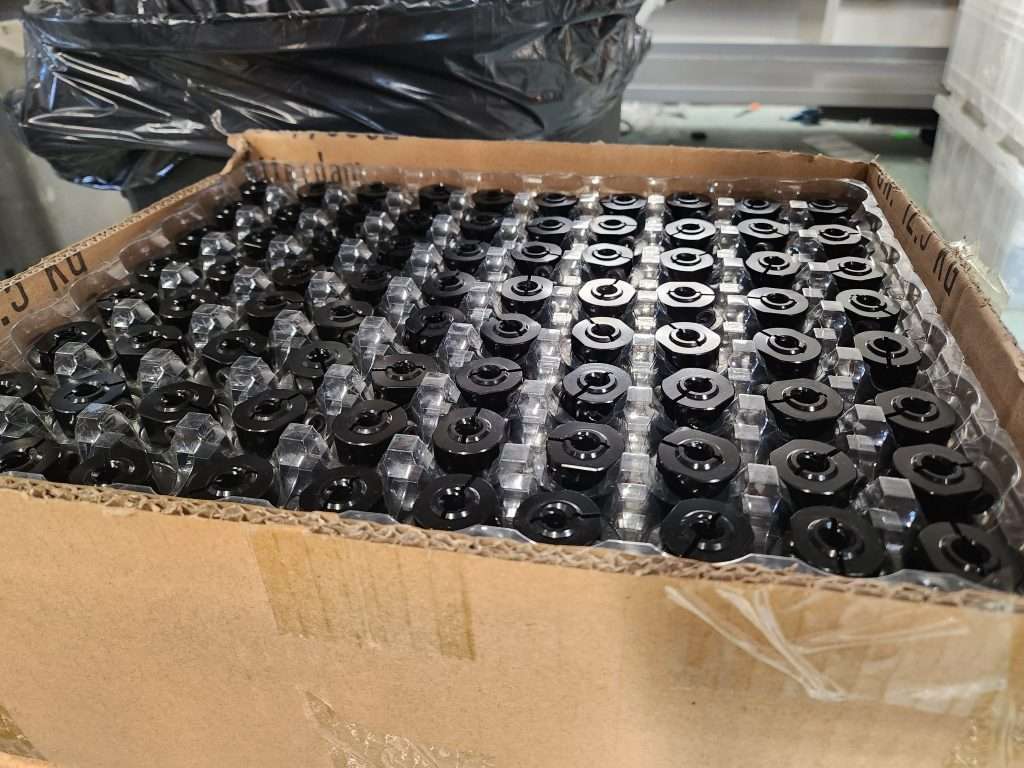
We’ve done some initial testing with 3D-printed nylon nuts, which have pretty good results, showing basically no backlash over testing. We’ve now ordered 400pcs (100 sets) of machined Delrin nuts. Our goal is to put them available for sale for people to use on their own machines. If they work well in the field we will switch to spring-loaded nuts as the default standard in LongMill kits.
I should include a disclaimer, which is that these are still a new, unproven product, and it is still possible that in the long term they may perform worse than the original nut.
We want to put these nuts out in the field so that we can get feedback and long-term testing done to validate the design. I’m very confident that this will make an improvement to the overall experience of using the LongMill, but before we make the switch, we want to make sure that we do some real-life testing.
There may be some small tweaks we may consider making, such as adjusting the spring force and length and spacing of the arms, which may happen based on the beta testing.
For this first batch of nuts, we will collect some survey data to help understand the experience of the user. At this current stage, we only have T8-size nuts, but we may expand it to the T12 size as well.
July was a bit of a slow month due to the Vancover port strike holding up shipments for us to ship LongMills in the queue. However, now that parts are back to arriving again, we’re picking back up with our regular routine.
We have a lot of news to cover, especially with the pending release and shipping of the Vortex Rotary axis and new development around the SuperLongBoard.
Want to get news like this directly in your email inbox? Make sure to sign up for our mailing list.
UPS reaches labour deal with Teamsters before strike
This July, we found out that Teamsters working for UPS were preparing for a strike in August, which would have disrupted shipments going to the US. However, UPS and Teamsters have settled on a new UPS contract which increases worker wages across the board and improved working conditions.
We are happy to hear that a resolution has been made, especially as we get into the busiest part of the season for our business.
LongMill and Extension Kit Orders
July has been a slow month for us shipping out LongMills as we have been affected by the port strike that delayed our shipment of controller boards. However, I’m happy to announce that we will receive the boards today and expect to clear the queue in the next 2 weeks.
The large majority of the pending 100 LongMill orders have been packed and are waiting to have the controller boxes done to have them shipped out.
Some LongMills waiting to be shipped
As some folks may know, we’ve continued to work on smoothing out the process of dealing with customs for shipments going to the US. Recently, we’ve been assigned a single contact with UPS to handle all of our LongMill shipments that need customs clearance going to the US. We found that some items were being miscategorized for duties and taxes, and we suspect it is because a big part of this is a manual process that causes human error. We believe that having a single contact who is familiar with the line items will speed up the clearance process with fewer mistakes.
A few new design updates on the LongMill MK2 design include a focus on phasing out of using M3 bolts in the assembly process and replacing them with M5 screws, including parts such as the couplers and ACME locking nuts. We are phasing out components using M3 screws in the LongMill assembly process because they are prone to stripping the heads more easily. Eventually, a full LongMill will be able to be assembled with just one M5 Allen key and our special wrench that we provide (as well as a drill and bit to mount your LongMill to a wasteboard of course).
Some new prototypes of the assembly wrench for new hardwareNew T8 locking nuts replacing the brass ACME nuts
We are also starting to use longer Z motor cables for the motors so that LongMill 48×30 kits, which are now the most popular variant, will not need a motor extension cable, simplifying the assembly process as well.
Additionally, now that the design of the LongMill MK2 has matured over the past year or so since its launch, we are moving to figure out injection molding parts for it for the first time. If you didn’t know, we 3D print several components for the LongMill MK2, including the dust shoe and feet. We found that due to the large number of feet we print, moving to injection molding would be a natural next step to reduce our need to rely on the 3D print farm, which is harder to scale production for.
We are entering into the first day of August with around 100 pending LongMill orders, but we expect to clear the queue in a week or two, after which we expect to shorten lead times again.
Vortex Rotary Axis
The last of the Vortex Rotary Axis parts have arrived at the end of July and we are now starting production and assembly!
First batch of machined parts looking beautifulTest assembly of the Vortex kitSwitch assemblies for Y axis to rotary mode
Our team has been continuing to work on different areas of the Vortex so that when they get into the hands of our users, they’ll have everything they need to get started. This includes:
Thorough assembly and installation instructions. We just completed initial trials and tests of the assembly process to make sure that we provide clear instructions to make it easy to put together. We found that everything came together really easily, except for the cam clamping system for the t-track, which we are currently working on to make it less finicky. We estimate that most users should be able to put it together in about 30 minutes. Full instructions will be found on our Vortex Resources soon.
Video content about the Vortex. We understand that not a lot of how-to and tutorial content exists for rotary CNCing. Our video production team and the engineers are working on the next steps for creating content so that our users can learn how the Vortex works and how to use it.
The gSender team continues to work on completing Rotary Axis implementation into the gSender, including homing and visualization for rotary. These features will be in gSender Edge at the time of launch and will be merged into the main version of gSender down the line. You try and learn about the latest version of Edge here.
We will start to trickle out Vortex Rotary Axis kits over the next week or two as we iron out the last bits of details. We expect the first batch of kits to start shipping out at the end of this week or early next week.
LaserBeam
LaserBeam production continues to move along smoothly, with most orders shipping out within a few days. We have stock available for the LaserBeam ready to ship now.
SuperLongBoard
Work for the SuperLongBoard (SLB) continues on. The team has been able to successfully test the main functionality with excellent results. However, we found our initial tests with the onboard compute module to be unsuccessful, as the Broadcom and Rockwell-based processors used on smaller compute modules to not be powerful enough to accommodate the visualization of g-code directly onboard.
Revised SLB
While additional software development was able to make significant speed improvements, we felt that the compute module would most likely need more headroom in the future if we were to implement other features down the line such as having a camera monitoring system, which we felt would be difficult to add due to a limitation of system resources.
We have now started looking at higher power compute modules, single board computers, and other hardware that we feel would ensure that the onboard gSender experience would be smooth and seamless, as well as provide headroom for future applications. However, the downside is that higher-power computers also cost more, and while our initial budget was around $80CAD/60USD for the compute module, we expect the computers to cost somewhere around $100-$200USD depending on the specs and configuration.
That being said, since we don’t need to have certain components and other parts to support the onboard computer directly, some of the cost of the computer is offset by the lower cost of the SLB itself.
We’ve decided to split the development of the SLB into two parts, one for the board itself, which will use grblHAL, a new, more advanced firmware and all of the improved motor control and drivers, and the computer itself. This means that the computer will live off the board in one fashion or the other.
While it would have been really cool to have the whole system integrated, we believe that by dividing and conquering, we can have the main portion of the SuperLongBoard out of the development process and into production first, and focus on the computer addition after. We felt like we could tackle some of the main problems with the current LongBoard with the new controller, and that it would be better to have the improvements we’ve already developed reach users sooner rather than having everything wait on further development on the onboard computer side.
This means that users will still need to connect their computers to the board to control their machines when the first batch of SLBs release, but better communication protocols, electronics, and shielding will make the USB connection significantly more reliable than before. Andrew, our main developer on this project, assures me that unreliable connections that cause issues with some users with the current board will be a thing of the past.
This version of the SLB natively supports communication over Ethernet, as well will have onboard storage which allows for streaming onboard rather than through a cable, which will improve reliability as well.
We are making the final design changes to prepare this version of the SLB for prototype production, and we hope to have production boards available near the end of the year. If you want to learn more about the SLB, please read: https://sienci.com/2023/04/10/first-look-at-the-superlongboard/
The Vortex Rotary Axis* will be available on June 1, 2023, at 1 PM Eastern Standard Time, where the first 300 units will be available for pre-order.We expect to ship in August 2023.
New videos and content coming out for the Vortex soon! Make sure to sign up for our mailing list, for new updates and other Sienci-related news. Subscribe to our Youtube channel where we’ll post more videos on the Vortex Rotary Axis in the new few weeks!
*After much debate, we have decided to call the name for this new add-on the Vortex Rotary Axis
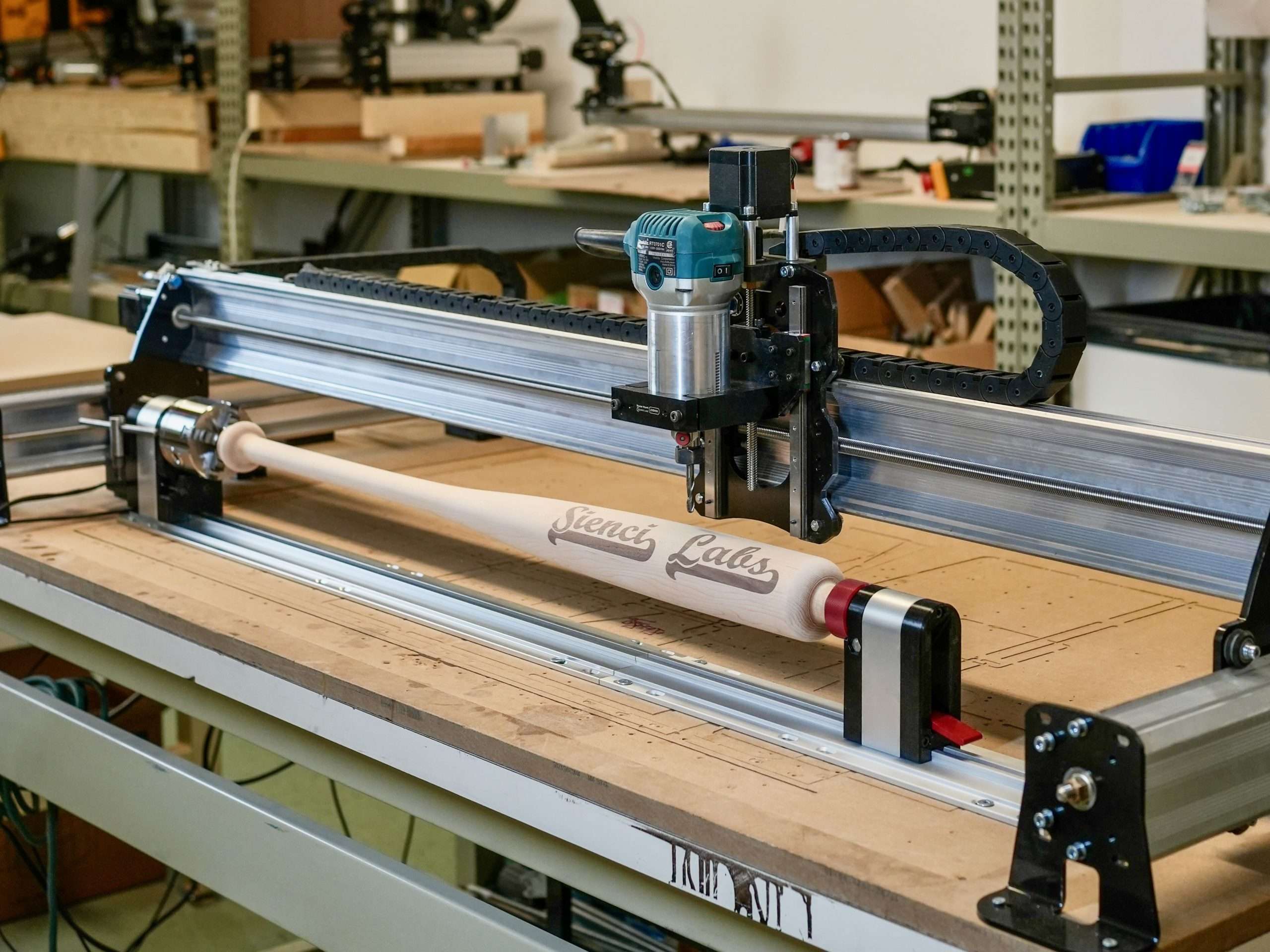
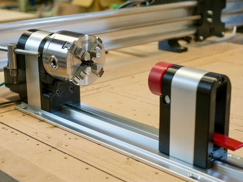
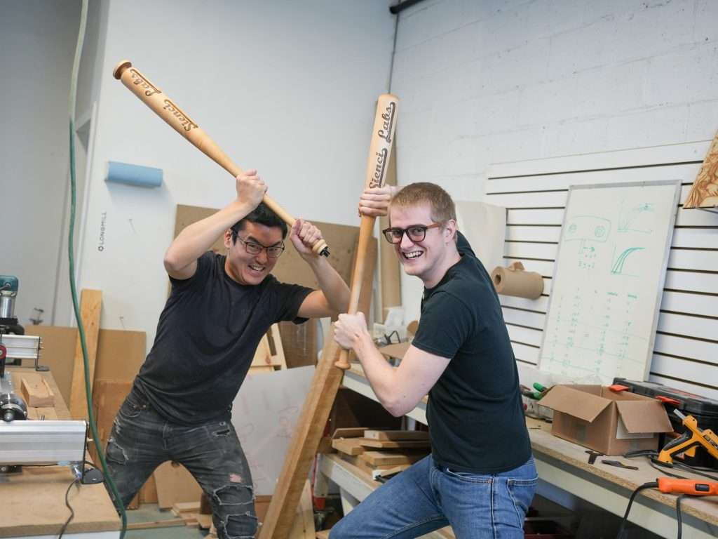
It’s been a long journey for developing the Vortex Rotary Axis, but we’re finally excited to share a launch date for our new add-on! This new product aims to make doing rotary projects like making bats, wands, furniture legs, bowling pins, and other turn-able projects with your LongMill and the Vortex.
The Vortex is unique in that not only is it a compact, precise, high-quality rotary axis we designed from scratch, but our direct integration into gSender also plans to add functionality not found in other CNC systems. Additionally, just like all our products, the Vortex will be supported by our team with high-quality tutorials and resources to make it easy to install, learn, and use your rotary axis.
The Vortex can be integrated, plug and play, in any standard LongMill CNC**, and comes with the hardware, electronics, and instructions to help you find success with CNC rotary carving!
**With the exception of the 12×12 LongMill MK1. Integration for the Vortex Rotary Axis on 12×12 machines may require moderate modification to fit.
Video Content
What is a Rotary Axis?
The Vortex Rotary Axis is an add-on created to allow users to integrate a rotary axis into their LongMill.
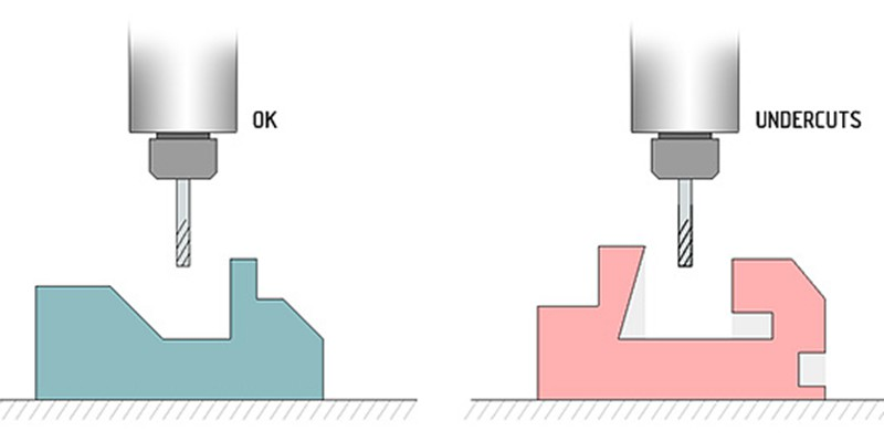
Most CNC routers like the LongMill use a 3-axis system, which consists of an X, Y, and Z linear motion system that is used to position bits and end mills. One of the limitations of a 3-axis system is the fact that 3-axis machines cannot make “undercuts” without flipping or material manually. Since the machine only can orient the bit vertically, there are limitations to the types of geometry it can carve.
To address these limitations, CNC machines can come with additional degrees of motion, typically including a 4th or even 5th axis. In the case of the LongMill, a rotary axis positioned along the X direction allows the machine to turn a part as the X and Z axis can move in sync as the material turns and rotates.
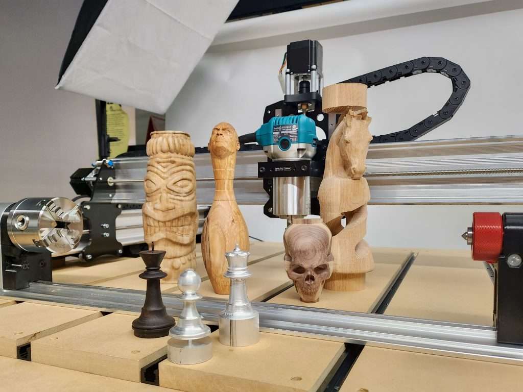
On a mechanical level, the 4th axis for the LongMill will come with a chuck to hold the material as well as a series of bearings and pulleys connected to a stepper motor to rotate the material as the machine carves. This allows for users to make projects like:
Bats
Chess pieces
Furniture legs
Wands
Figurines
Busts
and more!
Production and Pricing
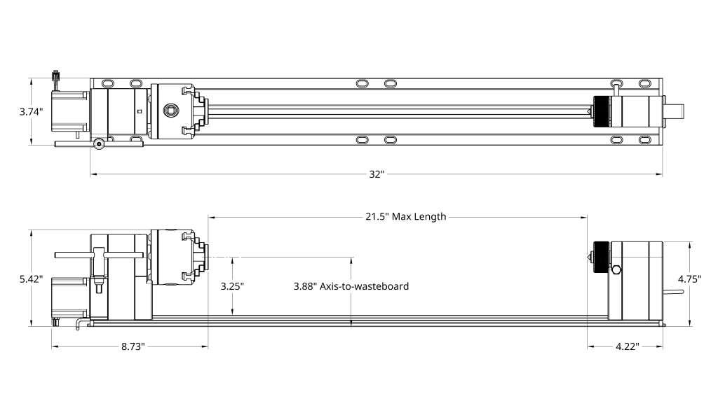
Each Rotary Axis will come with all of the hardware and electronics to integrate the kit into any existing LongMill CNC.
The Rotary Axis will start at:
$600CAD/$449USD – For 12×30 and 30×30 LongMills
Dimensions below.
$640CAD/$469USD – For 48×30 LongMills
Dimensions below.
The main difference between the two options is the rail track extension that allows users to mill larger items corresponding with the X-travel range on each version of the LongMill.
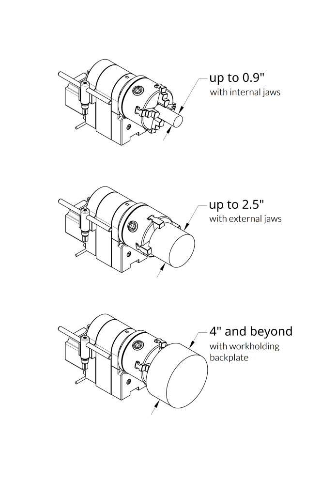
All options will come with a standard jaw that can hold material in several configurations:
Additionally, customers should budget purchasing rotary axis ready CAM software, such as:
DeskProto Multi-Axis Edition (€249.00 for the hobbyist edition, €995.00 for commercial)
*Based on our testing, we strongly suggest Vectric software for its simplicity and user friendliness.
Resources and Support
It’s important for us to stress that the Vortext Rotary Axis follows our philosophy for providing a complete product, not just hardware, but high-quality support, resources, instructions, and tutorials to make sure users are able to use their rotary axis to the fullest.
We’ve recognized that not only are affordable rotary axis options are limited in the hobby CNC space, but the resources needed to learn it also are lacking. We’ve taken the initiative to provide support through the Vortex.
Did you know that we regularly post tutorials and educational content for the LongMill on our Youtube channel? Make sure to check it out and subscribe to us if you haven’t yet!
Production Timeline
The Rotary Axis is already in production, with parts expected to complete and arrive between June and July. We are expecting a late July to mid-August shipping date. Please note that because this is a pre-order, timelines may change due to delays and unexpected circumstances. We will continue to share production updates for the Rotary Axis on a regular basis on the blog here, so that customers can sign up for our mailing list, for new updates and other Sienci-related news.
Development Timeline
Mechanical and electrical design and development of the Vortex Rotary Axis is now complete, and we are currently waiting on production parts to complete and arrive. Our engineering team is currently working on stress testing and resource development, as well as preparing for assembly, QA, and packaging for the final product.
The software development team continues to finalize the development of the software support in gSender, such as implementing new features and getting testing feedback from users of gSender Edge. We expect basic functionality to be available at time of shipping, and we will continue to add more features in future releases of gSender.
FAQ
When will the Rotary Axis ship?
Production on the Rotary Axis is currently ongoing, with the first units expected to ship in Late July to August 2023. For general development and production updates, please check our Blog. Orders will ship in the order in which they are placed.
What is the between the 48in and the 30in versions?
These lengths describe the track width for the rotary axis. Customers should purchase the size that matches with the working width of their LongMill.
When do you take payment?
We take the full payment immediately. Customers may cancel their order for a full refund anytime before their order ships.
What happens when all 300 units are sold out?
Based on early demand, we’ll decide on when we’ll start building a new batch. Turnaround times to build each batch takes about 3 months, so there may be a few months wait time additional once the first 300 units are sold out.
Will I get a notification or email before my order is ready?
Yes, we’ll send you an update email to let you know that your Rotary Axis is ready to ship.
Which machines is the Rotary Axis compatible with?
The Rotary Axis is designed to be compatible with all versions of the LongMill, with the exception of the LongMill MK1 12×12, due to the track width (however it can be modified to work).
We will be providing full assembly resources for the Rotary Axis.
Although users may be able to integrate the Rotary into other hobby CNC machines, we will only be providing compatibility and support for LongMill users at this time.
How is the Rotary Axis driven?
In the current configuration, the Rotary Axis uses the X-axis and Z-axis to move along the rotational axis of the material, with the Y-axis drivers disconnected and reconnected to the Rotary Axis motor to provide rotational movement. This means that in this configuration, the system is not a full 4-axis machine, but more of a 2-axis + rotary system. Each kit will come with a switch to toggle 3-axis and rotary axis modes.
In the future, we are planning to provide full simultaneous 4th axis motion through the SuperLongBoard, expected to launch at the end of the year (at an added cost).
Does the Rotary Axis come with software?
We’ve implemented gSender to integrate the ability to control, set up, and home the Rotary Axis. Users will need to use or purchase CAM software that supports rotary carving. We recommend VCarve Desktop or VCarve Pro, as this is the software that we primarily use and do testing on.
Can I order other items alongside my Rotary Axis?
For logistical reasons, we strongly recommend users to place separate orders for the Rotary and other items. However, if you place an order for other items with the Rotary, we will ship them separately based on the stock availability of the items.
When your Rotary Axis is ready to ship, if you wish to order additional items to ship together with combined shipping, please Contact Us for assistance.
Hey everyone, I’m excited to share with everyone a project that Chris and the rest of the Sienci Labs team have been working on in collaboration with Andrew and his team Expatria Technologies to develop a new CNC control board and firmware system. The SuperLongBoard (SLB for short) represents a huge step in hobby CNC technology, as it’s advanced electronics and software bring not just new features and functionality to the LongMill, but at a price point that we believe will be affordable for hobbyists.
LongMill running at 10,000mm/min and 750mm/s^2The SuperLongBoard taking its first baby steps
What is the SuperLongBoard?
The SuperLongBoard is a next-generation control board for the LongMill CNC. This development gives access to a whole new set of features, functionality, and integrations more commonly found in industrial applications to the hobby CNC market. Some features and functionality include:
Full integration of gSender within the control board, removing the need for a separate computer to run the CNC
Advanced, programmable stepper drivers that run motors faster, quieter, and with more torque
Faster, more accurate motion control processing for smoother movements
Ability to control more than 3 axis, for full 4th and 5th axis motion control
Networking and file transfer with wifi and ethernet, USB port and SD card for removable storage, HDMI output for display outputs, and more
Standard PWM control for laser and spindle, with compatibility with industry-standard RS485 protocols for industrial-level spindle control
Rapid tests using the SuperLongBoard
Additionally, this design will have many input-output connections and ports to allow for new features and accessories to be used with the new board, effectively future-proofing your machine for years to come. Some of these features include:
Automatic tool changing support
Skew, cutter, and joint compensation
External wired and wireless pendant control
Camera and machine vision for features like failure and crash detection, auto zeroing, auto-tracing, and more
Please note that although these features are something we want to work on down the line, we currently do not have specific timelines on these features and they will not be available during launch.
You can even set up the SuperLongBoard to send messages through Slack!
The SLB is a system of two different parts working together. The first is the board itself, which contains all of the core functionality. This includes motor control, sensor inputs and outputs, and lower-level processing of g-code. Users will be able to tether this part of the controller directly to the computer using a USB cable in the same way as the original LongBoard currently used in all LongMills to control their CNC machines.
SLB takes things to the next step with the addition of an onboard compute module. The SLB has a small connection interface at the bottom of the board that allows for a compute module to be attached and replaces the computer or laptop. Users can connect a keyboard, mouse, and monitor to control all functions of the machine directly through the SLB.
The SLB can operate with and without the compute module. I expect that given the considerably low price of the compute module over a computer, around $40-80 dollars plus the cost of the monitor, keyboard, and mouse, as well as the extra speed, user experience, and reliability of an onboard system. But we are planning to allow for the board to be used in either configuration.
This control board will be backward compatible with ALL LONGMILL CNC MACHINES OF ALL GENERATIONS, which means that users can upgrade their machine’s capabilities by simply replacing the controller. All of the hardware and software will come ready to go, plug and play for all LongMill CNCs, and will have a similar form factor to the current LongBoard so that it can be integrated easily into your existing machine.
Why the SuperLongBoard?
The creation of the SLB comes with a series of motivations. The first and main motivation is our belief that at this current stage, the integration of smarter, more reliable, and more capable CNC control electronics will make the biggest improvement to the CNC user experience.
This new design will aim to eliminate many common issues universal to hobby CNC at this time, including:
Electromagnetic interference issues
Computer, compatibility, and connection-related issues
Resonance and driving issues restricting motor performance
With the integration of an onboard computer and far more sophisticated electronic systems, the SLB will not only be able to eliminate these issues, but it will also allow us to have better control of the hardware and software to optimize every aspect of the board and iron out bugs more easily.
As some readers know, we’re also in active development of the rotary axis. The SLB will also open up more possibilities for integrating new add-ons and improving already existing add-ons such as the AutoZero touchplate and LaserBeam. Some other potential add-ons include:
Plug-and-play router or spindle with programmable speed control
Bitsetter
Toolchanger
Plasma cutter
There are no specific development timelines for these items, but the SLB will allow for better compatibility for add-ons such as the ones listed above.
Development of the SuperLongBoard
The SuperLongBoard has been in development since the Fall of 2022. We’ve received our first batch of prototype boards and have been working with Andrew to develop the firmware and software for the control boards, finalize the PCB design, and prepare them for long-term beta testing.
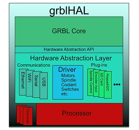
The development of the SLB actually comes with many different individual developments that all work hand in hand. First is the integration of grblHAL, a rewrite of GRBL that was originally designed to work on Arduino-based controllers. One of the limitations of GRBL was that since it was designed to work on low-performance microcontrollers, it has limitations on what features that could be added. Additionally, there are limitations on things like how many processes could happen at any given point and the raw speed of the processing of g-code and motor signals.
grblHAL essentially uses something called a hardware abstraction layer (HAL). The HAL is essentially like a switchboard that the GRBL core knows how to use the microcontroller to communicate with different aspects of the board, such as the spindle control, motor drivers, and networking. This means that the development of core firmware that includes all of the functionality can be developed and only the HAL needs to be adapted to each model of the microprocessor. This means that the development of grblHAL benefits the whole community since features that are developed for one controller can be implemented on other controllers almost immediately with basically no modification. grblHAL, although still fairly new, already has a fair number of plugins that can be used to add functionalities.
The next part of the development is with the gSender integration into the SLB and to use grblHAL. Since the plan is to integrate gSender directly on the compute module, we are working on optimizing it for the hardware, such as improving the general performance and UI, adding new features and functionality, and testing the speed and reliability of gSender as a whole. We’re already working on the new gSender, and you can find an early access version here.
And lastly comes the design and production of the PCBs themselves. At this stage, we’ve mostly finalized the design of the board and are making the last few touches to the design and layout. The new control board uses a larger number of components, adding to the challenge and complexity in manufacturing, but we’ve been able to work closely with PCB manufacturers for the first batch of prototypes and expect this area to come along relatively smoothly.
We are expecting to work on testing the boards in-house for the next few weeks and start beta testing in the next coming months.
Pricing
At this time, we’re expecting the manufacturing and production cost of the SLB and case to cost around $100 (prices here in CAD). The compute module is expected to cost between $40 to $80 depending on the model and spec, bringing the total cost of production to around $150.
Chris and I have been talking about the pricing and how we want to figure this out, but we do have a few goals:
To offer it with new LongMill machine kits with minor changes to the current price
To have a simple and inexpensive upgrade path from the original LongBoard to the SBL
Reduce buyers remorse for currently existing customers
Here is our tentative pricing. Please note that pricing may change and is not set in stone.
SuperLongBoard, onboard computer, and enclosure: $280CAD/$210USD
This would be the full package with everything you need to plug and play with any LongMill. This also includes the onboard computer. Users who wish to use the onboard computer will need to provide their own monitor, keyboard, and mouse.
If you want to mix and match parts, you can use the pricing estimates below:
SuperLongBoard only: $180CAD/$140USD
For users that only want to upgrade the controller, but do not have the onboard computer. This would mean that you would still need to connect a laptop or computer to your controller. This also doesn’t include the price of an enclosure, so users can either make their own or integrate it with an existing enclosure. The case for this version of the controller is not backward compatible with the original LongBoard currently used in the MK1 and MK2 LongMills.
Onboard computer: $80CAD/$60USD
The onboard compute module is essentially a Raspberry Pi CM4 or another compute module of the same form factor. There are many different versions of CM4 form factor modules, all of which have different price ranges and specs. The price points of these modules vary greatly, which means the specific cost of this will be tied to which module we decide to choose. This would be available to users who choose to start with the SuperLongBoard and decide to add the onboard computer later in the future.
Enclosure: $30CAD/$23USD
The enclosure serves to protect the controller from dust and damage, as well as provide some mounting options onto the LongMill.
What’s next?
With regard to the LongMill
Once we get the SuperLongBoard into production, customers will be able to order them from our store to upgrade their machine electronics or as the controller that ships with new LongMills.
Here is our current general plan:
Once the SuperLongBoard is launched, to offer the original LongBoard and SuperLongBoard as separate options. The option for the original LongBoard would be the same, and the SuperLongBoard option would be a little more expensive.
Once we run out of or decide to phase out the original LongBoard, all new LongMills will ship with the SuperLongBoard.
For existing LongMill customers, we may provide a coupon so that users who wish to upgrade to the new controller can do so at a lower cost.
Based on where we are in current development, we expect SLB available sometime in the late fall or winter of 2023.
The exact details and pricing will come later.
With regards to other CNC machines
Given how powerful and integrated the SuperLongBoard is, we expect other CNC users to want to integrate the board with their own machines. While the board itself isn’t expected to cost a lot, given the complexity of support, resources, and documentation, we expect that a significant consideration in terms of support and price point will come down to many different factors.
We do plan on releasing the board designs open source as we have done for all of our hardware and software, which means that even if we don’t provide any official support, users who want to tinker should be able to figure out how to integrate things.
Here is our current general plan:
Users who want to use this board for other machines will be able to purchase it from our store, but they will not receive any technical or setup support. We will provide resources that we feel will be adequate for an experienced user to use for setup. At some point, we may also set up an online community where people can help each other.
In the future, there may be a certain tipping point in terms of scale for us to offer specific machine support, or if a third party decides to provide support themselves.
SuperLongBoard Survey
If you want to help contribute to our development for the SLB, please feel free to do our survey!